How to Perform Secondary Well Control While Drilling
Secondary Well Control
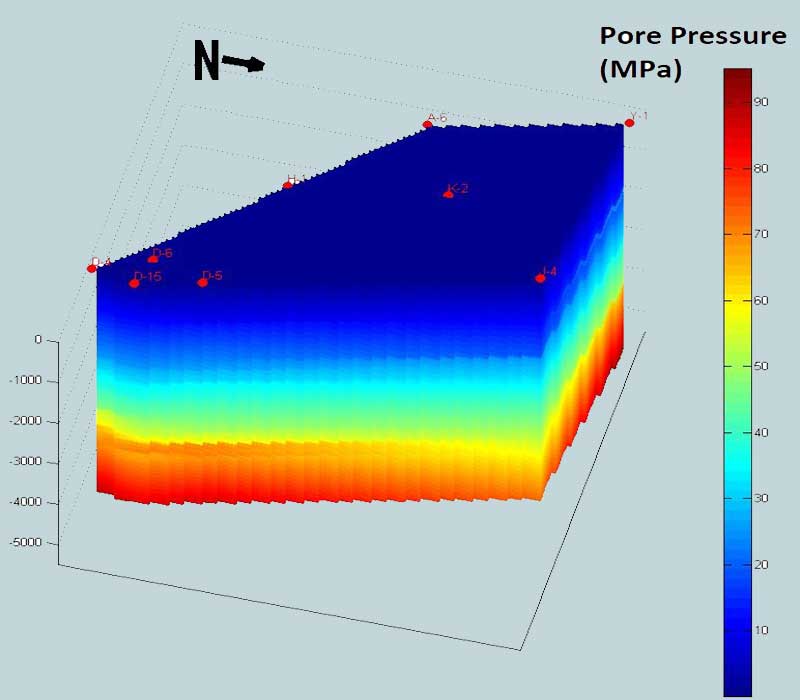
If due to any reason hydrostatic pressure in the well bore falls below the formation pressure, formation fluid may enter in the well bore (Kick) and if so happens, the primary control may be temporarily lost and a proper use of blowout preventers and kill procedures will provide Secondary well control, or in other words secondary well control involves detection & safe handling of kicks so as to re-establish primary well control.
Positive Kick Signs
In addition to kick warning signs that was discussed previous in the post on how to carry out primary well control: https://geodatadrilling.com/blog/2023/01/05/how-to-carryout-primary-well-control-while-drilling/ A Positive kick indicators are different from kick warning signs. They indicate that the kick has already entered the well bore. For any of the following positive kick sign, a flow check is required.
Increase in return flow (Pumps On)
After the early warning signs, the first positive kick sign is increase in flow rate at the flow line with pumps on. The entrance of any fluid into the well bore causes the flow rate to increase.
Flow from well (Pumps Off)
Stopping the pump causes a reduction in bottom hole pressure equivalent to the annular pressure drops, so flow check is a reliable method of checking for a well kick. If the well does not flow when the pump is shut off and remains static for two or three minutes, then no well kick is entering.
Pit Volume Increase
An increase in pit volume is obvious & positive indication of flow into the well bore & can be easily verified. If an increase in pit volume is seen, shut off the pump and make a flow check. If the well does not flow, no kick is entering.
Decrease in Pump Pressure and Increase in Pump Stroke
In case of kick there is under balanced condition between the fluid in the drill pipe and the mixed column of mud and influx in the annulus. Therefore, circulating pressure gradually decreases and unless the pump throttle is changed, pump speed slowly increases.
When one or more positive kick signs are observed, flow check is made. In case of self-flow, well can be shut-in. Blow Out Preventer is an equipment use to shut-in well and provide secondary well control.
Surface Well Control Equipment – BOP
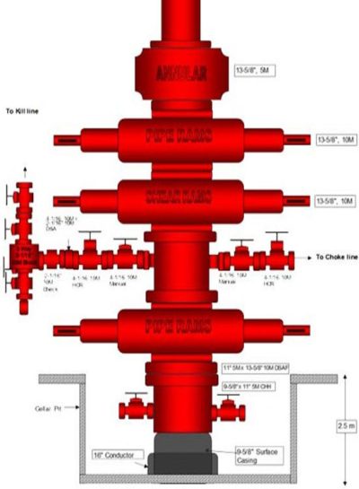
Annular
Consist of a single doughnut shaped element which, when pressurized by hydraulic fluid, will close on any object in the well. Most annulars are ‘well bore pressure assisted’ in that the force up helps the packing element to close in the well. The energy to close the rig BOPs is hydraulic fluid supplied via an accumulator system. If this hydraulic system fails, annulars will have a tendency to open unless check valves are placed in the closing line. Annulars are not designed to hold pressure from above.
Pipe Rams
Consist of two specifically sized elements which will close on the body of a specific size of tubular but not its connections – a derivative of this is a variable bore pipe ram (VBR) which are used to close around tubulars of different sizes within a limited range.
Pipe rams are not designed to hold pressure from above – subsea pipe rams particularly are designed to support the weight of a drill string. They are designed to stay closed if hydraulic power is lost from the line to the closing chamber and will automatically open when the opening chamber is activated, or in the case of one type can be locked and unlocked separately. Surface pipe rams can be closed manually.
The normal operating pressure of ram preventers is 1500 psi. 3000 psi can be applied by utilizing a bypass valve on the hydraulic accumulator unit on the surface unit. A separate circuit is used subsea for 3000 psi closing pressure for shear rams.
The main components of ram preventers are:
- Ram assembly including seals, and ram
- Ram shaft
- Bonnet
- Piston
- Operating cylinder
- Side outlets
Blind Shear Ram
Blind Shear Ram will close and seal on open hole and cut tubular in the well or, if no tubular is present, it will seal on open hole. Blind rams without the shear facility will not cut pipe. It is good practice to test blind/shear rams with the range of pipe likely to be used in the well, clearly the shearing blades in most cases will have to be replaced if used in anger or after testing their cutting capability.
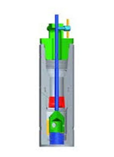
Safety Valves – Kick While Tripping
If the well kicks whilst tripping then a safety valve will have to be stabbed to secure the drill stem first before closing a blow-out preventer (BOP). These are sometimes called inside BOPs (IBOPs). Both valves need crossovers for the particular size of tubing and a quick and efficient way of stabbing the valve safely.
Surface Hook-up of Well Control Equipment
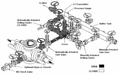
A typical surface hook up is shown in Figure 3. The choke manifold is a high-pressure routing device rated to the same working pressure as the stack. It should have at least two variable valves called chokes, one manual and one remote hydraulic, controlled from a choke panel positioned on the rig floor.
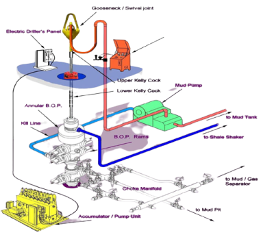
Valves on the kill line side, at the left of the spool, are closed during normal operations. The one on the right side of the spool is open during normal operations. The HCR (High Closing Ratio) valve is opened and closed remotely from the BOP panel at the rig floor. Fig 3 is a panel showing the schematic of the stack and all BOPs can be closed from the BOP panel or directly from the accumulator-closing unit.
Shut in procedures – Surface stack
In all cases, when the pumps are being used, eg. drilling ahead, the pump(s) are kept running until just before the BOP is closed. This enables the annulus pressure loss (APL) element of the circulating pressure to aid the BHP against the formation pressure and should help minimise the kick size. It is imperative that the well is closed in with the least gain (kick size) – particularly when the kick fluid is gas which will give the largest annulus pressures compared to a liquid kick – when circulating the kick fluid out of the well
Hard Shut-in – Surface Stack
- Pick-ups off bottom until first tool joint above rotary table (Kelly).
- Switch off pump(s).
- Close BOP.
- Open HCR to read annulus pressure and read drill pipe pressure. (This procedure according to API RP59 – therefore either annular or ram can be closed – if ram then tool joint must be clear off pipe ram.)
- Note kick size (pit gain).
Fast Shut-in – Surface Stack
- Pick up off bottom as hard shut in.
- Switch off pump(s).
- Open HCR valve.
- Close annular BOP.
- Read drill pipe and annulus pressure and record pit gain.
In both hard and fast shut-in methods the chokes are closed as part of the pre-kick choke manifold line up.
Soft Shut-in
The pre-kick choke manifold line up for the soft shut in includes all lines open to the mud/gas separator – this includes the designated choke which is also open.
The only valve isolating the circulating system from the mud/gas separator is the HCR.
- Pick up off bottom until first tool joint above rotary (if Kelly).
- Switch off pumps.
- Open HCR.
- Close annular BOP.
- Close choke.
- Read drill pipe and annulus pressure and note kick size (pit gain).
Companies will choose which shut in procedure to use for their operations. However, the evidence to suggest hydraulic shock by shutting the well in too quickly is not evident. This is the reason given for the so-called soft shut in. It means more gain – which is undesirable.
The hard shut-in is the quickest method of shutting in the well but the HCR is not opened until the well is shut-in. This could put a shock into the choke line if the annulus pressure is excessive. Not so excessive for surface stacks with relatively short choke lines, but not advisable for subsea stacks with longer choke lines.
The fast shut in is probably the least contentious, with potentially less gains than the soft shut more gain compared with the hard shut-in, but less shock to choke line than hard shut- in.
In nearly every case, the valve behind the choke is closed when the well is shut-in, this adds extra security and ensures no further influx if the variable choke is leaking.
Clearly the soft or hard shut-in could be used but, as explained earlier, the fast shut-in has fewer chokes line shock than hard shut-in and less kick volume than soft shut-in.