Borehole drilling, Soil investigation, Geophysical, Environmental, Oil and Gas

Category: Geotechnical – Soil Testing

Soil Classification for Engineering purposes

Soil classification is the arrangement of different soils with similar properties into groups and subgroups based on their application.

Soils may be classified in a general way as:

  • Cohesive vs. cohesionless
  • Fine- grained vs. coarse grained
  • Residual vs. Transported

However these terms are too general and cover too wide range of physical and engineering properties.

A more refined classification is necessary to determine the suitability of a soil for specific engineering purposes.

Therefore, these terms are collected into SOIL CLASSIFICATION SYSTEMS, usually with some specific engineering purpose in mind.

Most of the soil classification systems that have been developed for engineering purposes are based on simple index properties such as particle-size distribution and plasticity.

NEED FOR SOIL CLASSIFICATION SYSTEMS

  • A soil classification system represents, in effect, a language of communication between engineers.
  • It enables one to use the engineering experience of others.
  • The engineering properties have been found to correlate quite well with the index and classification properties of a given soil deposit.
  • Therefore, by knowing the soil classification, the engineer already has a fairly good general idea of the way the soil will behave.

Why more than one Classification System are in use?

  • Classification systems are used to group soils in accordance with their general behavior under given physical conditions.
  • Soils that are grouped in order of performance for ONE SET of Physical CONDITIONS will not necessarily have the same order for performance under other set of physical conditions.
  • This led to classifying soil by use, and each agency (Like FAA, AASHTO, USBR) has in mind specific use for the soils.

SOIL CLASSIFICATION SYSTEMS

The two major systems used at present are AASHTO and USCS. Both systems take into account the particle-size distribution and plasticity.

  • The AASHTO classification system is used mostly by highway departments. Geotechnical engineers generally prefer the Unified system USCS

A. AASHTO CLASSIFICATION SYSTEM

  • The AASHTO soil classification system was originally developed in the late 1920’s (1929) by the U.S. Bureau of Public Roads (BPR) for the classification of soils for highway subgrade use.
  • It was developed as a result of the work of Hogentogler in the 1920’s.
  • Adopted by Bureau of Public Roads in 1931.
  • AASHTO : Acronym of American Association of State Highway and Transportation Officials.
  • Originally, the system classified soil as being either a group A or a Group B.
  • A Group A soil was able to maintain uniform pavement support at all location whereas the Group B soils were not.
  • The B designation was subsequently deleted, leaving only A soils in the classification system.
  • Consequently, the “A” still remains in an AASHTO classification of a soil type, but it no longer has any real significance.
  • The A soils were subdivided into eight subgrade soil groups. A-1 through A-8.
  • It went through various revisions since 1929, and the classification system received its last revision in 1974.
  • ASTM D-3282; AASHTO method M145

REMARKS

  • According to this system, soil is classified into eight major groups, A-1 through A-8.
  • Soil group A-8 is peat (very organic) or muck (thin very watery, and with considerable organic material).
  • A soil is classified according to the table by proceeding from left to right, top to bottom, column by column on the table to find the first group in which the soil test data will fit.
  • The first group from the left into which the test data will fit is the correct classification.
  • The classification process stops at this point regardless if another column farther to the right can also qualify.

B. UNIFIED SOIL CLASSIFICATION SYSTEM (USCS)

  • This system was developed by Arthur Casagrande in 1942 for use in the air field construction works undertaken by the Army Corps of Engineers during WW II.
  • To make it applicable to DAMS and other constructions besides airfields, it was revised in 1952 in cooperation with the USBR.
  • The system was last revised in 1984 by the ASTM by the addition of a GROUP NAME to the group symbol. This modification has not been adopted by some agencies which use USCS to classify soils.
  • ASTM Test Designation D-2487.

This system is the most popular soil classification system among geotechnical engineers.

  • This system classifies soils under three broad categories:
  1. Coarse-grained soils < =50% passes sieve No. 200
  2. Fine-grained soils > 50% passes sieve No. 200
  3. Organic
  • Criteria for USCS:
  1. Grain size
  2. Cu, Cc
  3. Plasticity (Plasticity chart)
  • Tests required
  1. Grain-size analysis
  2. Liquid Limit
  3. Plastic Limit

Comparison of the USCS and AASHTO Classification Systems

  • In AASHTO if 35% passes No. 200  fined-grainedèIn USCS if 50% passes No. 200 fined grained
  • In AASHTO Sieve No. 10 is used to separate gravel from sand, in USCS it is Sieve No.4.
  • In USCS, the gravely and sandy soils are clearly separated, in the AASHTO system they are not.
  • The symbols GW, SM, CH and others that are used in the USCS are more descriptive of the soil properties than the A symbols used in the AASHTO system.
  • The classification of organic soils such as OL, OH, and Pt has been provided in the USCS. In AASHTO system, there is no place for organic soils. (A-8 has been taken out).
  • In AASHTO PI is used to distinguish between silt and clay (LL appears only in distinguishing A-7-5 and A-7-6). In USCS both PI and LL (plasticity chart) are used.
  • USCS distinguishes high and low plastic fine-grained soils.
  • Both AASHTO and USCS are better than most other available systems when applied to engineering or construction applications.
  • Both AASHTO and USCS systems have the advantage of having been used for many years and having gained acceptance in the engineering and construction fields.

Talk to us for your upcoming project in Soil Testing

Geodata Evaluation & Drilling LTD. offers Geotechnical Soil Testing services. Let us handle the project for you. contact us at www.geodatadrilling.com Phone: +234 8037055441

Soil Tests for Shallow Foundations

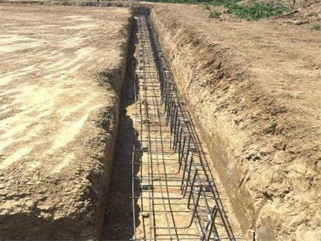
Index properties soil test should be conducted for shallow foundation. Refer to article on Types of Soil Tests for Building Construction. Additional Tests are required to determine allowable bearing pressure for settlement consideration:

Standard penetration test 

The standard penetration test (SPT) is performed during the advancement of a soil boring to obtain an approximate measure of the dynamic soil resistance, as well as a disturbed drive sample (split barrel type).
The procedures for the SPT are detailed in ASTM D 1586 and AASHTO T-206. The SPT involves the driving of a hollow thick-walled tube into the ground and measuring the number of blows to advance the split-barrel sampler a vertical distance of 300 mm (1 foot). A drop weight system is used for the pounding where a 63.5-kg (140-lb) hammer repeatedly falls from 0.76 m (30 inches) to achieve three successive increments of 150-mm (6-inches) each. The first increment is recorded as a “seating”, while the number of blows to advance the second and third increments are summed to give the N-value (“blow count”) or SPT-resistance (reported in blows/0.3 m or blows per foot). If the sampler cannot be driven 450 mm, the number of blows per each 150-mm increment and per each partial increment is recorded on the boring log. For partial increments, the depth of penetration is recorded in addition to the number of blows. The test can be performed in a wide variety of soil types, as well as weak rocks, yet is not particularly useful in the characterization of gravel deposits nor soft clays.

Standard Penetration Test

Consolidation test 

The one-dimensional consolidation test provides one of the most useful and reliable laboratory measurements for soil behavior. The test determines the compressibility parameters (Cc, Cs, Cr), stiffness in terms of constrained modulus (Dr = 1/mv), preconsolidation stress (Fpr ), rate of consolidation (cv), creep rate (C”), and approximate value of permeability (k) is conducted if the settlement of clayey layers calculated on the basis of liquid limit and in-situ void ratio indicates that settlement may be critical. Consolidation test is not required if the superimposed load on foundation soil is likely to be less than pre-consolidation pressure (assessed from liquidity index and sensitivity or from un-confined compressive strength and plasticity index).

Plate load tests 

The plate load test is a field test, which is performed to determine the ultimate bearing capacity of the soil and the probable settlement under a given load.

For performing this test, the plate is placed at the desired depth, then the load is applied gradually and the settlement for each increment of the load is recorded. At one point a settlement occurs at a rapid rate, the total load up to that point is calculated and divided by the area of the plate to determine the ultimate bearing capacity of soil at that depth. The ultimate bearing capacity is then divided by a safety factor (typically 2.5~3) to determine the safe bearing capacity

The test is applicable in cohesionless soils and  soils where neither standard penetration test or consolidation test is appropriate such as for fissured clay, clay with boulders etc..

Talk to us for your upcoming project in Soil Testing

Geodata Evaluation & Drilling LTD. offers Geotechnical Soil Testing services. Let us handle the project for you. contact us at www.geodatadrilling.com Phone: +234 8037055441

Types of Soil Test for Road Construction

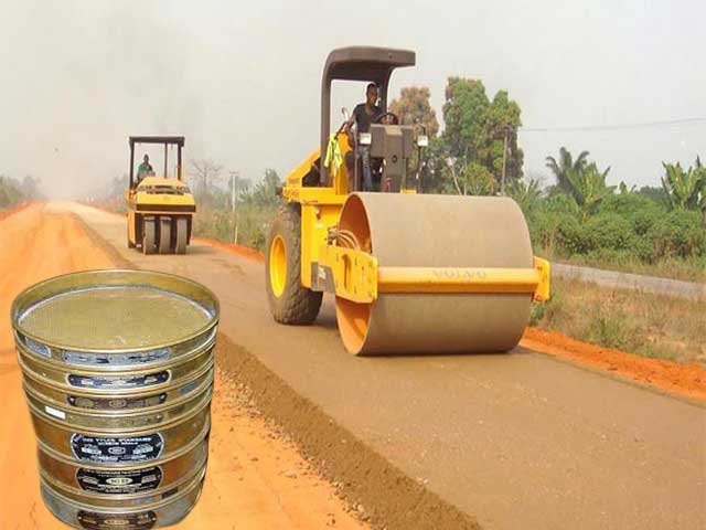
Do you have a stake in road construction and you want to ensure a stable and durable road from the construction company? Continue reading.

Road construction project requires site investigation to be carried out to understand the soil profile which affect road or pavement stability and durability. The soil tests include laboratory tests and in-situ tests.

In addition to the test on index properties of soil. Refer to article on Types of Soil Tests for Building Construction. California Bearing Ratio (CBR) Test is conducted to measure the relationship between force and penetration when a cylindrical plunger is made to penetrate the soil at a standard rate. The following are test for index properties of soil:

Particle size distribution (Sieve Analysis)

Specific gravity

Liquid limit and plastic limit tests (Atterberg test)

Moisture content test

Compaction test (Proctor’s test)

Classification of soil

California Bearing Ratio (CBR) Test

California Bearing Ratio test can be conducted in laboratory with remoulded sample or undisturbed sample in the field as an arbitrary strength test which is considered to stress soils and replicate wheel loads;

 CBR test is a measure of resistance of a material to penetration of standard plunger under controlled density and moisture conditions.

In CBR Test a cylindrical plunger of 50mm diameter penetrate a pavement component material at 1.25mm/minute. The loads for 2.5mm and 5mm are recorded. This load is expressed as a percentage of standard load value at a respective deformation level to obtain CBR value.

The harder the surface, the higher the CBR value. Typically, a value of 2% equates to clay, while some sands may have a CBR value of 10%. High quality sub-base will have a value of between 80-100% (maximum).

The CBR test is carried out on soils with a maximum particle size of 20mm. Tests are normally carried out at surface level or at depths of between 500-1000mm in 20-30m intervals along the proposed construction centerline. A minimum of three tests are usually carried out at each site.

Talk to us for your upcoming project in Soil Testing

Geodata Evaluation & Drilling LTD. offers Geotechnical Soil Testing services. Let us handle the project for you. contact us at www.geodatadrilling.com Phone: +234 8037055441

Types of soil test required for your building project – Be guided.

Types of soil test required for your building construction project when you commission a Geotechnical engineer or Engineering Geologist for Soil testing

Various tests on soil are conducted to determine the quality of soil for building construction. Some tests are conducted in laboratory and some are in the field. Here we will discuss about the importance of various soil tests for building construction. The tests on soil are as follows.

Moisture content test

Atterberg limits tests

Specific gravity of soil

Unit Weight / Dry Density Test on Soil

Compaction test (Proctor’s test)

The grain size distribution (Sieve Analysis)

Unconfined Compressive Strength of Soils/ Triaxial Strength

Standard Penetration test

Classification of soil

Moisture content test

The moisture content or water content of soil is the ratio of mass of water to mass of soil which is expressed in percentage. Oven Dry Method is commonly used to determine the water content of soil in laboratory. The moisture content is used in determining the bearing capacity, settlement and also give an idea of the state of soil in the field.

Atterberg limits tests

At low moisture the soil will behave as a solid, but with increasing moisture, it becomes plastic. With excess moisture it will flow like a liquid.  This is very important when trying to build on these type of materials.  The two commonly determined Atterberg Limits represent the moisture contents at which a specific soil’s behavior changes from solid to plastic (Plastic Limit) and from plastic to liquid (Liquid Limit).  The numerical difference between the liquid limit (LL) and the plastic limit (PL) is called the Plasticity Index or PI which is the moisture content range over which the soil will behave in a plastic manner.

In combination, the LL and the PI are used to differentiate (classify) silts and clays of high and low plasticity.  In the field, the Atterberg Limits, can be used as a guide indicating how much a soil is likely to settle or consolidate under load. If the field moisture is near the liquid limit, a lot of settlement is likely. The opposite is true if the field moisture is near or below the plastic limit.  . 

To measure the critical water content of a fine grained soil, Atterberg provided 3 limits which exhibit the properties of fine grained soil at different conditions. The limits are liquid limit, plastic limit and shrinkage limit. These limits are calculated by individual tests.

Specific gravity of soil

The Pycnometer is used for determination of specific gravity of soil particles of both fine grained and coarse grained soils. The determination of specific gravity of soil will help in the calculation of void ratio, degree of saturation and other different soil properties. The major measuring equipment in this test is Pycnometer. This is a glass jar of 1 litre capacity that is fitted at its top by a conical cap made of brass. It has a screw type cover. There is a small hole at its apex of 6mm diameter. The leakage is prevented by having a washer between the cap and the jar.

Unit Weight / Dry Density Test on Soil

The calculations of overburden stresses within a soil mass require evaluations of the unit weight or mass density of the various strata. The measurement of unit weight for undisturbed soil samples in the laboratory is simply determined by weighing a portion of a soil sample and dividing by its volume. This is convenient with thin-walled tube (Shelby) samples. The water content should be obtained at the same time to allow conversion from total to dry unit weights, as needed. Unit weight is defined as soil weight per unit volume (units of kN/m3) and Soil dry density is measured as mass per volume (in either g/cc or kg/m3). In common use, the terms “unit weight” and “density” are used interchangeably.

Dry density of soil is calculated by core cutter method and sand replacement method.

Core Cutter Method: Cylindrical core cutters of 130mm long and 100mm diameter are used for testing the in-situ compaction of cohesive and clay soils placed as fill. By using core cutter method, bulk density of soil can be quickly calculated and by determining the moisture content of the soil the dry density of the fill can be calculated and hence the voids percentage. A high percentage of voids indicates poor compaction of soil. A cylindrical core cutter is a seamless steel tube. For determination of the dry density of the soil, the cutter is pressed into the soil mass so that it is filled with the soil without disturbing the core contents. The cutter filled with the soil is lifted up. The mass of the soil in the cutter is determined and the dry density is obtained.

Sand Replacement Method: The sand replacement test method is used to determine in situ dry density of soil. This test is of significant importance and it has been widely used in various construction project sites.

The field density of natural soil is required for the estimation of soil bearing capacity for the purpose of evaluation of pressures on underlying strata for computation of settlement, and stability analysis of natural slope.

The sand replacement test method is also used to determine the in-place density of compacted soil in order to compare it with the designated compaction degree, hence it specifies how much the compaction of the soil is close to the designated compaction degree.

Compaction test (Proctor’s test)

Proctor’s test is conducted to determine compaction characteristics of soil. Compaction of soil is reducing air voids in the soil by densification.

Need for Determining Optimum Moisture Content (OMC) of the Soil

The soil at the construction site must be stable enough to carry the loads from the structures through footings without undergoing undesirable settlements during the construction process and during the service period.

The construction site is hence treated and compacted based on the site investigation report. The amount of compaction required for the soil in the respective area varies from site to site.

To determine the amount of compaction required by the soil and the optimum water content for compaction, the compaction tests are conducted on the soil from the site in the laboratory.

The standard Proctor Compaction test was developed by R.R Proctor in 1933. Proctor showed that:

The soil moisture content and the degree of dry density to which the soil is prepared to be compacted maintain a definite relationship.

The Optimum moisture content (OMC) or Optimum Water Content (OWC) is the moisture content at which the soil attains maximum dry density. This OMC value is with respect to the specific amount of compaction energy applied to the soil.

The scope of the Standard proctor compaction test is to determine the relationship between the moisture content and the density of the soil that is compacted in a mold with a rammer of 2.5kg dropped at a height of 305mm.

Relationship between maximum dry density and optimum moisture content of soil can be obtained from soil compaction curve obtained from Standard Proctor Compaction Test. This relationship helps in determining the optimum water content at which the maximum dry density of soil can be attained through compaction

The grain size distribution (Sieve Analysis)

In sieve analysis, percentages of various grain sizes are determined. The grain size distribution is used to determine the textural classification of soils (i.e., gravel, sand, silty clay, etc.) which in turn is useful in evaluating the engineering characteristics such as permeability, strength, swelling potential, and susceptibility to frost action.

Wash a prepared representative sample through a series of sieves (screens). The amount retained on each sieve is collected dried and weighed to determine the percentage of material passing that sieve size.

Unconfined Compressive Strength of Soils/ Triaxial Strength

Unconfined Compressive Strength determines the undrained shear strength (cu) of clay and silty clay soils. Trialaxial Strength determines strength characteristics of soils including detailed information on the effects of lateral confinement, pore water pressure, drainage and consolidation. Triaxial tests provide a reliable means to determine the friction angle of natural clays & silts, as well as reconstituted sands. The stiffness (modulus) at intermediate to large strains can also be evaluated.

Standard Penetration test

The standard penetration test (SPT) is performed during the advancement of a soil boring to obtain an approximate measure of the dynamic soil resistance, as well as a disturbed drive sample (split barrel type).

The procedures for the SPT are detailed in ASTM D 1586 and AASHTO T-206. The SPT involves the driving of a hollow thick-walled tube into the ground and measuring the number of blows to advance the split-barrel sampler a vertical distance of 300 mm (1 foot). A drop weight system is used for the pounding where a 63.5-kg (140-lb) hammer repeatedly falls from 0.76 m (30 inches) to achieve three successive increments of 150-mm (6-inches) each. The first increment is recorded as a “seating”, while the number of blows to advance the second and third increments are summed to give the N-value (“blow count”) or SPT-resistance (reported in blows/0.3 m or blows per foot). If the sampler cannot be driven 450 mm, the number of blows per each 150-mm increment and per each partial increment is recorded on the boring log.

Classification of soil

Soil classification is the grouping of the soil with similar engineering properties into a category based on index test results; e.g. group name and symbol. Classification tests can be performed by the laboratory on representative samples to verify identification and assign appropriate group symbols

Talk to us for your upcoming project in Soil Testing

Geodata Evaluation & Drilling LTD. offers Geotechnical Soil Testing services. Let us handle the project for you. contact us at www.geodatadrilling.com Phone: +234 8037055441

A Guide to soil testing – What lies beneath your Land

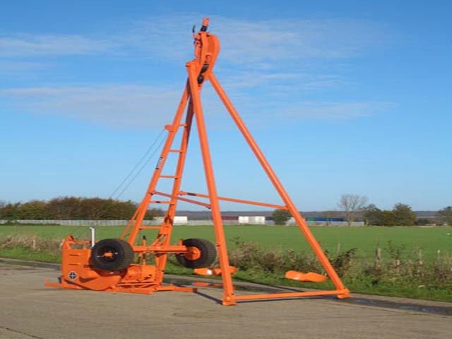
It is essential to have your soil tested and a report prepared before you start building your home or any construction work. Every block of land is different and if you have a report detailing the various soil conditions, you can use this report to select the depth and type of foundation suitable for a given structure to avoid problem of collapse building. A foundation failure of a major structure is measured in millions of money; it can even lead to loss of life. An ignorant or misinformed Engineer and builder can lose millions in unanticipated costs. Such mistakes often lead to major lawsuits that drag on for years and cost everyone except the lawyers. Here, I will discuss the process of soil testing, the roles of the engineer, building contractor and what you need to know before any construction work is undertaken.

KNOWING YOUR SOIL

Knowing what type of soil you have on your site enables your engineer to make the best possible decision about the suitable type of foundation for safe and long lasting building or structure. It’s hard to know what happened to the land before your purchase. Your block of land could be very different from the one next to you and a soil test is the best way to understand your ground condition.

By understanding your soil and knowing what lies beneath, you can make good and informed decisions during the building design process. Sadly, too many people forgo soil testing, decide to gamble and let the builder start digging the foundations. This can lead to expensive-to-resolve problems, such as finding out that the foundations have to be installed much deeper than originally planned due to expansive and collapsible soil, or hitting a water table, which necessitates having the engineer design a different foundation solution. This typically falls back onto the home or structure owner as their responsibility — and as an extra cost.

The way to prevent such an unwelcome situation is to commission a geotechnical investigation, sometimes referred to as a soil test or site investigation. Geotechnical investigation reports vary depending on where the property is, what type of building is going to be built or what requirements are set by the local council authorities.

WHAT IS EXAMINED?

Geotechnical report with basic clues that must be understood to make an informed good judgment of the soil conditions for a client will include:

Soil boring equipment utilize for soil testing.

The bore hole or test pit is advanced with a variety of equipment. Bore holes advanced with an auger means that the ground can be excavated with normal earthmoving equipment, i.e. backhoes, scraper, bulldozers and the like. Bores that are made with pneumatic, carbide tipped drill or similar rock drill means that blasting or heavy ripping will be required. Test pits are usually dug with a backhoe. The size of the backhoe makes a huge difference as to how easily the ground can actually be dug. A small rubber tired backhoe-loader will show refusal (unable to dig) on soils that can be readily excavated with large track mounted backhoes or heavy equipment.

Recommendations for construction methods

If the report is concerned with settlement, liquefaction and suggests over-excavation; that usually means weak clayey soils. While these soils may be easy to dig, they may also be unsuitable for backfill and wet and sticky. Even though clayey soils may appear to be firm enough to drive on, they can start to pump with repeated heavy-wheeled traffic. This is when the moisture is worked toward the surface by the equipment pounding and turns the top layer to mud and the equipment will get stuck. If this condition is present it may be necessary to build aggregate haul roads. Rain and snowmelt will turn clays to mud and may be difficult to dry out enough to travel on.

Soil boring logs

The boring logs will detail the soil layers by depth from the surface or by elevations. The log will contain such information as: soil classification, relative denseness of the soil, sampling points, sample recovery, water content, dry unit weight, blow counts per foot and ground water depth, drill refusal and if well casing was needed. Often the soil descriptions are subjective by being based on the experience and judgment of the observing geologist. How dense or hard the soil is often based on how quickly the drill can be advanced. The description is often based on the look, feel and sometimes smell or taste of the soil. The boring logs are a good place to start to understand the soil properties. The boring logs should be plotted on the drawings and on cross sections so the relationship of the excavation, structures is scaled to the soils and water table. If casing of the hole was necessary, it usually means the ground is too weak to stand on a normal construction excavation slope.

Soil description (classification such as silty-sand)

This will usually identify the soil by classification of particle sizing such as cobble, gravel, sand, silt, or clay, etc. Most soils are a combination of these classifications, meaning there is a gradation of material. Sand and larger grains are often referred as cohesionless soils. Without clay or silt fines sand, gravel and cobbles will not have cohesion (glue) to bind the soil and give it shear strength. Soils with clay or silt are often referred to as cohesive soils, as they are capable of developing significant shear strength

Soil bearing capacity

How strong the bearing capacity of the soil: Soils are measured for their allowable bearing pressure. The allowable bearing pressure is the soil’s ability to carry the load of a building and its contents without excessive settlement.

Soil properties (hard, stiff, dense, loose, etc.)

Usually soils are described as loose, dense, hard, stiff, soft, etc. The relative density terms of: loose, dense are applied to sands and gravels. Terms such as soft and stiff are usually applied to clays and silts. Hard can mean rock or cemented soils, although if the soils are cemented the geologist will usually mention that fact. Loose or soft ground means that the ground may not support a slope as steep as 1H to 1V. Dense sands or gravels are no guarantee that the gravels will stand on a steep excavation slope, as they may be tightly packed but have little or no fines to cause cohesion. Cemented soils can be caliches, volcanic tuff, or pyroclastic ash. These soils can be some of the most difficult and expensive materials to excavate. They can have a relatively low density and show as being relatively soft rock. However, they tend to absorb blasting energy and almost impossible to penetrate with a ripper tooth.

Boring depth

Usually the boring logs are advanced well below the planned excavation depth to insure that accurate formational trends can be plotted and no weak layers are present near the foundation grade. When the borings are terminated above or just at the planned excavation depth, you must be very wary. This means you cannot be sure of what may be encountered at the bottom of the excavation. Is there going to be rock or water that must be handled? Did an obstruction halt the drilling effort?

Boring refusal

This is usually indicated at the bottom to the boring log, if it occurs. If all refusals are well below the planned excavation depth, it will not be a major concern. If a small percentage of the borings have met refusal in the excavation limits it usually means that there are isolated obstructions. It is not possible to determine what the obstruction is unless the soils report or site history reveals the object. A small isolated boulder can stop an auger drill and be of little concern. On the other hand, it could be a ridge of solid rock that will be expensive to remove.

Blow counts

This is a very important measure of soil properties. This is a standard penetration test where a 140-pound weight is dropped and the number of blows to advance the point one (1) foot is counted. Obviously the more the blows the harder the soil. Loose or soft soils will show blow counts of less than 10. Blow counts of 10 to 50 blows per foot usually mean the ground will be fairly easily excavated. When the blow counts are over 50 but less than 100, ripping of the ground is very likely. When blow counts exceed 100, the ground may be very difficult to excavate and require blasting or hoe ram effort.

Soil moisture content

Optimum compaction moisture is usually between 8 and 15% of the dry weight of the soil. Ground water will show about 25 to 40% moisture by weight of the dry soil. Supersaturated clay can be 50% water. Those are oozing mud that will not support the weight of even low ground pressure tractors. Optimum water content in the soil causes some cohesion, helps to control dust, and allows easy compaction effort.

Soil dry density

Normal soils will have dry densities between 95 and 130 pounds per cubic foot (pcf). Solid rock and heavy metallic ores can have densities exceeding 150 pcf. Loose cohesionless sand will usually have a density of about 90 pcf. Volcanic cinders can be as low as 50 pcf. Soil density by itself tells little about the soil properties. Volcanic tuff can have a density of less than 100 pcf and be some of the most difficult material to excavate. Dense rock that is fractured and/or weathered can often be easily excavated.

Particle distribution curves (sieve analysis)

This test will show the grain size distribution of the various soils. A well-graded soil will have a uniform grain size distribution from gravel to clay. A poorly graded soil will have the grain concentrated around a single grain size. Dry sands and gravels that contain less than about 10% clay can be almost completely cohesionless, meaning that while they are easy to excavate, they pull apart to a slope flatter than 1H to 1V. Over sized rocks such as cobbles and boulders should be indicated. The oversized material may have to be screened out for the soil to be used as backfill or embankment. If there is more than about 25% clay, the soil may be unsuitable for backfill or embankment. Unless the soil is very dry, it is difficult to screen clay out of soils because it clogs the screen. Clay can be removed by washing but it is a slow expensive process generating a lot of very dirty water that can be difficult to get rid of.

Soil Types:

The basic soil types are:

1. Clays and silts: These are soils where the grains are less than 0.005 inches in size (less than #200 sieve size).

2. Sands: The grain sizes are between 0.25 and 0.005 inches in size. (#4 to #200 sieve size)

3. Gravels: The grain sizes are between 4 inches and 0.25 inches in size. (4″ to #4 sieve size)

4. Cobbles: These are rounded rocks that are between 12 and 4 inches in size.

5. Boulders: These can be over 20 feet in size.

6. Rock: Massive formations that require blasting or heavy ripping to excavate.

7. Any combination of the above. Most soils usually contain more than one soil type, for instance, a soil classified as sandy-gravel is gravel-containing sand.

Soil Classifications:

1. ML – Silt

2. CL – Lean Clay

3. OL – Low Plasticity Organic Soil

4. OH – High Plasticity Organic Soil

5. MH – Elastic Silt

6. CH – Fat Clay

7. GW – Well Graded Gravel

8. GP – Poorly Graded Gravel

9. GM – Silty Gravel

10. SW – Well Graded Sand

11. SP – Poorly Graded Sand

12. SM – Silty Sand

The soil classifications are often shown as the combined ones when no single classification is accurate. For example, GW-GC stands for well graded gravel with clay. The soil classifications are another step in the process, but they do not tell us how hard or soft the ground is or what excavation difficulties are to be expected. The soil classifications refer only to the grain size of the soil and little of the other ground properties.

Relative denseness of the soil:

Here we are getting to the point where the soil properties are described. Usually the terms: loose, soft, dense and hard are applied to the soil. Loose may mean running soils that will not stand on slopes greater than 1.5 Horizontal to 1.0 Vertical. Soft may mean clay with high water content and stable construction slopes may be difficult to maintain. Dense soil is usually the best material to work with because it will support the equipment, be easily excavated and steep construction slopes can be established. Hard soils probably require ripping equipment and slower excavation productions

Atterberg limits (liquid limits and plasticity index)

This is a series of tests for plasticity index and liquid limit that are applied to clays. These are a concern since the specifications may require that the backfill and embankment materials have limited plasticity and liquid limit. This requirement is designed to control swell and settlement as the moisture content of the soil changes. This can force the disposal of the excavated soil and the import of more suitable soil. Often the specifications are silent as to the suitability of the native soils for backfill and embankment, leaving it up to the contractor to determine if the soil should be used. If field tests show the soil unsuitable, then the contractor pays the extra costs. Another common requirement is the sand equivalent (SE) of the backfill material. That is a measure of what percentage of the soil acts as sand. Sometimes the soil’s report will not contain these tests, but the specifications will use them to define suitable backfill and embankment soils.

Compaction test (optimum moisture for compaction)

This is very valuable information. By comparing the optimum maximum compaction density with the in place native density, a reliable calculation can be made for how much the soil will shrink from the ground to compacted fill. Typically, the shrink is between 5 and 15% for most normal soils. Soils with high clay contents can shrink more than 25%. Blasted or ripped rock will often swell as much as 25% as it will go from a void ratio of zero to 25% or more. If the in-situ dry density of the soil is 100 pcf and the optimum density is 120 pcf, at 90% compaction the density of the embankment will be 108 pcf. The ratio of 100 pcf to 108 pcf shows an 8% shrink from in-situ to embankment. Usually it is a good idea to add a couple of percent of shrink to allow for settlement, over build and over compaction.

Direct shear tests

This is very valuable information. This test shows the friction angle and the cohesion of the soil. The friction angle is a measure of the angularity of the soil particles to resist rolling. Cohesion is the measure of the bonding of the soil particles in shear.

.Seismic Velocity Lines:

When the geologist finds or expects formational rock to be present, often seismic lines will be run. This test places several geophones in a long line. Then a charge or hammer blows induces sound waves into the ground. A computer analyses the time delays that are recorded at each geophone. This will show the depth to each stratum and the speed of sound through the stratums. The faster the sound travels through the ground the harder the rock. Soil with sound velocities of less than 3,000 feet per second (fps) is usually easily excavated. Rock over 10,000 fps cannot be ripped efficiently.

Most rock that can be effectively ripped lies in the 3,000 to 8,000 fps ranges. The sound velocity is a guide to ripping only. Very hard rock, such as granite, that is fractured and or weathered can sometimes be easily ripped. On the other hand, relatively soft rock that is monolithic, such as volcanic tuff and caliches, can be practically impossible to rip efficiently.

Permeability

This test is run to determine how quickly ground water will travel through the soil. Clean sands and gravels can transmit huge volumes and require massive pumping to lower the water table enough to work at the bottom of an excavation. Clays are impermeable and release the water slowly. Often the ground water is transferred through aquifers that are open-graded and very permeable. These aquifers can be capped with impermeable layers. There have been cases where dewatering wells were unnecessarily extended into aquifers and forced excessive pumping. These tests aid the experienced dewatering specialist in designing an appropriate dewatering system.

Soils that contain more than 30 to 40% clay will behave like clay because the clay will more than fill the natural voids of the larger particles. This means that the larger particles do not have direct bearing on each other and the failure plane is mostly through the clay fines. Clays can be some of the most difficult and undesirable soils to try to work with. Plasticity index and liquid limit are used to define Clays. Expansive or fat clays have plastic and liquid indexes about 50 or more. These materials will significantly swell and contract with the change in moisture content. This is often the cause of pavement failure, sidewalk buckling and foundation cracking. Clays can be plastic in that they can continue to settle under a foundation over a long term, causing cracks to develop long after the structure is completed.

Clays vary from being a viscous fluid to dense and stable material. Water content and relative compaction are critical to the soil properties. If there is too much water the clay becomes mud. If there is not enough moisture the clay becomes dust. Either condition causes the clay to be difficult to handle and compact. Even when the clay is at optimum moisture, it can be difficult to achieve the required degree of compaction. To add to the problem, it can be difficult to get the clay to dry out or accept additional water. Clays that contain high moisture content, above 20% or so may be unstable. The water instead of adding cohesion now becomes a lubricant, reducing the friction angle to nearly zero. This can result in catastrophic failure, with little or no warning. Rain or irrigation water that is allowed to pond can supersaturate the soil and cause a violent slide. Sometimes warning signs of impending failure will cracks forming in the ground parallel to the bank and/or sloughing, bulging and slumping of the bank slope. In short, clay is the least desirable structural and construction soil to work with.

Well-graded sands and gravels that contain 5% to 15% clay or silt fines can be the best materials to work with. They will excavate and compact easily. There are enough fines to hold the optimum moisture but will not continue to settle under structural loading. The fines and water will add cohesion and allow steep construction slopes.

Open or poorly graded dry sand and gravel can be difficult to work with. Open or poorly graded mean the grain size is concentrated at one sieve size. Clean dry beach sand is an example of such material and can be difficult to walk and drive through. It will not easily compact and added water quickly drains away.

Rock properties are often difficult to deduce from the geotechnical report. Although you may be able to tell if the rock must be shot or ripped from the descriptions and recommendations, it usually does not describe what the rock fragments sizes will be when excavated. Sometimes, the geotechnical sampler will have cores available for inspection. These cores will give you an idea of the texture, hardness, and natural joint spacing of the rock. Try to get a sample to hold, scratch it with a knife, and see if it breaks or crumbles easily. There is no better way to understand what the rock properties are than holding samples and observing the formation in place. Any soil can be in any state of consolidation and cementation. Sandstone was once sand dunes or river deposits that were compressed by over burden and cementing minerals leached into the formation over millions of years. Slate and shale were once mud on at lake or sea bottom. Lava is heat fused inert minerals that weather very slowly and is usually very hard, requiring blasting or hoe ramming to remove. There are thousands of minerals that make up millions of soil conditions. No two sites are exactly alike.

Only through study of the site-specific geotechnical report and a site visit can any real judgment of construction methods be made. It is also recommended that potholing with a backhoe be performed in the presence of the estimator for the project. Review the specifications to determine if the soil is suitable for backfill. The sieve analysis may show there is oversize that must be screened out. There may be too much clay fines. The Atterburg properties or sand equivalent may make the in-situ soil unsuitable and the material must be over excavated and/or disposed of offsite and suitable material bought and imported.

Failure to understand the geotechnical report has caused many a financial disaster. The contractor must bid aggressively to win work. It is better to know the real conditions and avoid costly mistakes that can cause a project to lose money out of pocket by ignoring or misinterpreting the information contained in the report. Each geologist will present his or her findings in different ways. Some reports are more thorough than others for several reasons. It is common to find that underground conditions vary from what was discovered by the test borings. At rare times the owner will even deliberately misrepresent the facts to gain lower bids. This usually results in a long expensive lawsuit over changed conditions that only the lawyers win.

Each soils report will contain a great deal of information. There is no one test or observation that will tell the contractor what is the best construction method for each site. Each test and observation is a clue. There are always dozens or even thousands of bits of information that must be scrutinized, analyzed, and correlated. This process can take several people weeks to prepare an excavation plan for a large project such as a dam. Only then can methods and productions be reasonably estimated.

Geotechnical reports always include disclaimers and warnings that the ground conditions may vary from those found in the borings and test pits. There is good reason for the disclaimers. Geotechnical work is still as much an art as it is a science. Any extrapolations derived from the reports are individual interpretations of what that person might expect to find. No one is able to see exactly what is under the ground surface. All the tests and observations only indicate probable trends that are often subject for debate between expert geologists.

Some information will need further examination, which is done by an accredited Geotechnical laboratory. Soil samples are taken from site and sent to the laboratory to complete a comprehensive soil analysis.

ROLE OF THE ENGINEER

The design engineer will review geotechnical report to know what is under the surface to support the structures. To that end, the engineer needs to know several critical soil properties to design the most suitable foundation solution:

What is the allowable soil bearing pressure?

What is the expected foundation settlement?

What is the active soil load?

What is the passive soil loading?

What is the sliding friction factor?

What is the potential for differential settlement?

What is the soil liquefaction potential during an earthquake?

What are the seismic design accelerations?

Where is the groundwater table?

What is a permanent stable slope?

Will piling be required?

Can the native soil be used for backfill?

What are the criteria for the pavement sections?

Are hazardous wastes present?

How corrosive are the soils?

Will there be voids, obstructions or unstable soils?

ROLE OF THE BUILDING CONTRACTOR

The building contractor wants to know what the subsurface conditions are so that an accurate estimate of costs and time can be entered into a competitive bid. To that end the contractor will search the soils report to determine the following:

Where is the ground water and how much water must be pumped?

Is there rock to be drilled and shot (sometimes blasting is not allowed)?

Can the ground be ripped with a bulldozer?

What excavation equipment and methods will be most effective?

Is there enough space on the job to store backfill materials?

Can the native material be used for backfill?

Will the native material need to be processed (screened/crushed) for backfill?

How much backfill must be bought and imported?

How steep can the temporary excavation slopes be cut?

Can obstructions be expected?

What compactive effort and equipment is needed for backfilling?

Will excavation shoring be required?

What is the most effective shoring method?

Will the ground stand long enough to use trench shores or shields for pipe trenching?

The answers to the above questions are given from the Geotechnical soil report? The report is directed mostly to the design engineer and the building contractor usually must make an interpretation of the information to develop a construction plan. This interpretation is often vital to the success of the project.

Talk to us for your upcoming project in Soil Testing

Geodata Evaluation & Drilling LTD. offers Geotechnical Soil Testing services. Let us handle the project for you. contact us at www.geodatadrilling.com Phone: +2348037055441

© 2023 geodata & Drilling

Theme by Anders NorenUp ↑