Pore-Pressure and Wellbore Stability analysis to mitigate High cost of unscheduled drilling events
A lack of accurate pore-pressure prediction and wellbore stability analysis can result in unscheduled drilling events, such as blowouts, kicks, hole washouts, wellbore break- out, and stuck pipe. Undetected abnormal pore pressure and wellbore instability also adds to drilling nonproductive time and increase drilling costs in millions of dollars and sometimes leads to abandoning the well before reaching its objective.
Integration of predrill pore-pressure and geomechanics analyses with real-time monitoring consistently provides an effective way to prevent drilling failure and improve well-construction efficiency.
Abnormal pore pressures can cause serious drilling incidents, such as unwanted fluid influx to wellbore (Kick) and well blowouts, if the pressures are not predicted accurately. This can lead to erroneous mud-weight design plan that can contribute to wellbore instability.
A lack of an accurate wellbore-stability prediction can also cause borehole breakouts and in hole closure, pack off, and collapse in cases of tensile and compressive shear failures leading to mud loss and lost circulation through hydraulic fractures and in severe cases can lead to a total lost borehole. Estimated cost to the drilling industry for hole stability problems range from 600 million to 1 billion dollars annually.

When the mud weight, or equivalent circulating density (ECD), is less than the pore pressure, the wellbore experiences splintering failure in shale formation. In this case, wellbore washouts or fluid kicks resulting from underbalanced drilling may occur.
A well may not have fluid kicks in an underbalanced-drilling scenario if impermeable formations that is not over-pressured are penetrated. When the mud weight or ECD is less than the shear-failure gradient or borehole collapse pressure gradient, the wellbore experiences shear failure (or wellbore elliptical enlargement, breakout, or collapse). Wellbore fracturing occurs when mud pressure exceeds the capacity of near-wellbore rock to bear tensile stress and the drilling fluid creates hydraulic fractures.
The drilling-induced fractures may cause drilling-fluid losses and even a total loss of drilling fluid returns (lost circulation). Maintaining wellbore stability and preventing these costly problems require an accurate prediction of the conditions that cause wellbore failures, including pore pressure and safe-mud-weight operating window.

Pore-pressure prediction
Pore pressure is the fluid pressure in the pore space of the formation. Pore-pressure analyses include three aspects:
- Pore pressure analysis before drilling a well include: Seismic data analysis and interpretation in the plan well location; Well-logging, and drilling data in offset wells if available
- Pore pressure analysis while drilling a well (qualitative and quantitative): Drilling parameters and mud-logging data; Logging-while-drilling (LWD) or measurement while-drilling (MWD) data
- Pore pressure analysis after drilling the well: Wireline log analysis (Sonic log, Resistivity log etc.)
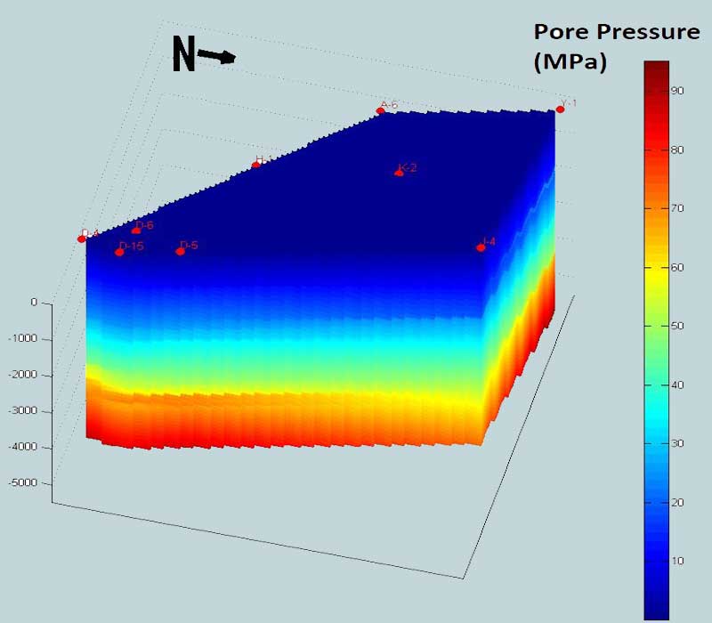
Pore pressure prediction from seismic data analysis before drilling
Bowers (1995) proposed that the seismic interval velocity and effective stress have a power relationship. On the basis of this relationship, pore pressure can be obtained from seismic interval-velocity data (Reflection times to transit times) in the planned-well location. The seismic data transform in terms of depths interval velocities and interval travel times are used for pressure gradient calculation for determination of (Overburden pressure and gradient, Pore pressure and gradient, Fracture pressure and gradient).

Pore pressure prediction from wireline logs and logging while drillings logs
The analysis of wireline logs before drilling for offset wells and logging while drilling (LWD) allows the calculation of:
- Overburden pressure and gradient
- Pore pressure and gradient
- Fracture pressure and gradient
The wireline logs generally used for pressure prediction and evaluation are: Sonic Logs, Induction Logs (Resistivity Logs) and Density Logs.

Pressure prediction and evaluation from drilling and mud-logging data
The acquisition and interpretation of drilling and mudlogging data represent a very important group of techniques which have the advantage to be available more or less in real time while drilling. These methods can be:
- Qualitative: Which, if analyzed in their completeness, can provide significant information about the actual status of the well and alert the drilling team of dangerous and abnormal conditions while drilling. Among the qualitative techniques base on drilling and mudlogging data include:
- Drilling Rate
- ‘d’ exponent, Sigma log
- LWD (Resistivity, Density, Sonic)
- Drag and torque
- Mud pit level, Return flow, Pump Pressure (kick)
- After Lag Time: Gas, (BG, CG, Pump off Gas) MW (out), Cuttings Shape/Size, Lithology (anhydrite, known marker, etc.), Shale density, Shale factor, Temp(out)
These are discussed in : “Pore-Pressure and Wellbore-Stability Prediction for Prevention of Drilling incident”.
2. Quantitative: Which ensure the quantification of the pressures acting in and around the well and the related risk levels. These include:
- Overburden gradient calculation
- Formation Pressure calculation by:
- Equivalent Depth Method
- Ratios Method
- Eaton Method
- Fracture Gradient Calculation by:
- Eaton Method
- Daines Method
These are discussed in “Quantitative Methods of Real-Time Pore Pressure and Wellbore Stability Detection”.
After the wellbore – Near Wellbore Stress-State
Before drilling, rock stress is described by the in-situ stresses; effective overburden stress, effective minimum horizontal stress, and the effective maximum horizontal stress. These stresses are designated by (σ1, σ2, σ3).

As the hole is drilled, the support provided by the rock is removed and replaced by hydrostatic pressure. This change alters the in-situ stresses. The stress at any point on or near the wellbore can now be described in terms of: Radial stress acting along the radius of the wellbore; Hoop stress acting around the circumference of the wellbore (tangential); Axial stress acting parallel to the well path. These stresses are designated by (σr, σø, σz)

Hoop Stress σø
Hoop stress is dependent upon wellbore pressure, in situ stress magnitude, orientation, pore pressure, hole inclination and direction. Wellbore pressure is directly related to mud weight/ECD.
For a vertical wellbore with equal horizontal stresses, hoop stress is dependent upon the mud weight and the magnitude of the horizontal stresses and is equally distributed around the wellbore
A deviated well creates unequal distribution of hoop stress around the wellbore due to the redistribution of the horizontal and vertical stresses. Hoop stress acting on a cross-section of the wellbore is maximum at the sides of the wellbore perpendicular to the maximum stress. The same is true when drilling a vertical well in an in-situ environment of unequal horizontal stress. Hoop stress is maximum at the side of the wellbore perpendicular to the maximum horizontal stress.
Axial Stress σz
Axial stress is oriented along the wellbore path and can be unequally distributed around the wellbore. Axial stress is dependent upon; in situ stress magnitude and orientation, pore pressure, and hole inclination and direction. Axial stress is not directly affected by mud weight.
For a vertical well with equal horizontal stress, axial and vertical stress are the same. Axial stress in a deviated well is the resolution of the overburden and horizontal stresses.
Radial Stress σr
Radial stress is the difference in wellbore pressure and pore pressure and acts along the radius of the wellbore. Since wellbore and pore pressures both stem from fluid pressure acting equally in all directions, this pressure difference is acting perpendicular to the wellbore wall, along the hole radius.
Hoop (σø), radial(σr), and axial (σz) stress describe the near wellbore stress-state of the rock. Mechanical stability is the management of these stresses in an effort to prevent shear or tensile rock failure. Normally the stresses are compressive and create shear stress within the rock. The more equal these stresses, the more stable the rock.
Whenever hoop or radial stress become tensile (negative), the rock is prone to fail in tension. Many unscheduled rig events are due to loss of circulation caused by tensile failure.

Mechanical stability is achieved by controlling the parameters that affect hoop, axial, and radial stress.
Wellbore stability controllable parameters:
- Mud weight (MW)/Equivalent circulating density (ECD),
- Mud filter cake,
- Well path – Inclination and azimuth,
- Drilling / tripping practice.
- Time dependent effect
Mechanical stability of the well is also impacted by drilling fluid/formation interaction. Chemical instability eventually results in mechanical failure of the rock in shear or tension.
Effect of Mud Weight/ECD
Mud weight, ECD, and pressure surges on the wellbore directly affect hoop and radial stress. An increase in MW decreases hoop stress and increases radial stress. Similarly, a decrease in MW increases hoop stress and decreases radial stress. The result on wellbore stability is dependent upon the magnitude of the mud weight increase/decrease.
Mud Filter Cake and Permeable Formations
The filter cake plays an important role in stabilizing permeable formations. An ideal filter cake isolates the wellbore fluids from the pore fluids next to the wellbore. This is important for hole stability and helps prevent differential sticking as well.
If there is no filter cake, the pore pressure near the wellbore increases to the hydrostatic pressure; the effective radial stress is zero. The simultaneous decrease in effective hoop stress causes the stress-state to move left in the stability envelope; decreasing the stability of the formation. An ideal filter cake helps provide for a stable wellbore. The chemical composition of the mud and permeability of the formation control the filter cake quality and the time it takes to form.
Hole Inclination and Direction
The inclination and direction of the wellbore greatly impacts the stability of the well. Unequal distribution of hoop and axial stress around the circumference of the well tends to make the wellbore less stable.
For Equal Horizontal Stress: Drilling a horizontal well causes the hoop and axial stress distribution around the wellbore to change. Before drilling from vertical, the hoop stress is equally distributed. As angle increases to horizontal, the hoop stress on the high and low side of the wellbore decreases, but the hoop increases greatly on the perpendicular sides.
Bottom-hole Temperature
Temperature changes associated with mud circulation during drilling may alter the rock properties. The change in rock properties may reduce or enhance borehole failure depending on the thermal effect. Temperature fluctuations may also influence the stress distribution around the borehole. As the temperature increases, the tangential and vertical stresses will increase. However, temperature fluctuations will not influence the stress anisotropy around the borehole as the thermal effect should alter the tangential and vertical stresses by an equal amount.
Time-dependent effects.
Reactive shale instability is also time-dependent, and is governed by two intrinsic mechanisms: (a) consolidation and (b) creep. Consolidation is due to pore pressure gradients induced by fluid communication between the mud and pore fluid. Creep is described by a change of strain at a constant effective stress level. Both of these mechanisms will result in hole size reduction. In practice, it is difficult to distinguish between creep and consolidation effects. In general, consolidation will occur shortly after loading, while creep will govern later deformation. The mud pressure and properties, and the temperature in the rock may vary during drilling operations, which in turn enhance borehole instability. All these parameters make it more difficult to directly pursue the time-dependent effects. The best approach is to quickly isolate the rock with a casing to minimize the potential borehole instability.
Providing a stable wellbore
- Potential Stability Indicators
If the answer to any of the questions below is “yes”, preventive measures should be taken:
- Indications of tectonic activity in the area?
- Sudden pressure transition zones expected?
- Adverse formations expected (reactive shale, unconsolidated or fractured
- formations, abnormal or sub normally pressured zones, plastic formations?
- Is wellbore inclination greater than 30?
2. Identify Stress Regime
σ1= Greatest effective stress
σ2= Intermediate effective stress
σ3 = Least effective stress

3. Determine Magnitude of In Situ Condition (sv , sh , sH)
- Overburden – sv (Obtained from density logs of offset wells).
- Formation Pore Pressure -pp (Estimated by seismic and logs).
- Minimum Horizontal Stress – sh (Determined by LOT and/or logs).
4. Use Core Tests or Logs to Determine Formation Rock Strength or Use Logs to determine: Effective Compressive Stress. Rock strength is estimated through correlations with sonic density logs since slow sonic velocity and high porosity generally relate to lower rock strength.

5. Select Mud System and Determine Mud Weight Window: Stability spreadsheets and analysis tools are used to determine the mud weight window for each hole section.
6. Avoiding Stability Problems
- Select an inhibitive mud for reactive formations.
- Casing points should allow for mud weight windows determined from stability analysis
- Maintain mud weight/ECD in stability window. Use down hole. ECD monitoring tools in critical wells.
- Optimize well trajectory based on drilling days vs. stability.
- Plan for effective hole cleaning and stuck pipe prevention.
- Follow safe drilling practices. Control ROP, surge pressures.
Mechanical Stability
Mechanical instability has stated earlier is related to incorrect mud weight /ECD and/or well trajectory. Too low mud weight can cause hole cavings or collapse resulting in stuck pipe. Too high mud weight /ECD can cause excessive fluid losses to the formation or total loss of returns
Warning Signs of Mechanical Stability Problems
- Large size and volume of cavings over shakers.
- Erratic increase in torque/drag.
- Hole fill on connections or trips
- Stuck pipe by hole pack-off /bridging.
- Restricted circulation /increases in pump pressure.
- Loss of circulation.
- Loss/gain due to ballooning shales.
Preventing Mechanical Stability Problems
The constraints on wellbore pressure are dictated by formation pressure on the low end and fracture strength on the high end. Hydraulics planning must also consider minimizing the shock load imposed to the wellbore.
Measures to prevent/correct mechanical stability problems include:
- Increase the mud weight (if possible). The mud weight values should be determined using a stability analysis model and past experience if drilling in a known field.
- If drilling fractured formations, it is not recommended to increase MW. Increase the low-end rheology (< 3 RPM Fann reading).
- Improve hole cleaning measures. Maintain 3-rpm Fann reading greater than 10. GPM for high-angle wells equal to 60 times the hole diameter in inches and half this value for hole angle of less than 350.
- Circulate on each connection. Use back reaming and wiper trips only if hole conditions dictate.
- Minimize surge/swab pressures.
- Monitor torque/drag and the size and amount of cuttings on shakers.
Wellbore stability analysis
Borehole collapse could be predicted by adopting compressive failure analysis in conjunction with a constitutive model for the stresses around the borehole.
The most commonly used failure criterion in wellbore stability analysis is Mohr-Coulomb criterion This criterion involves only the maximum and minimum principal stresses, σ1 and σ3, and therefore assumes that the intermediate stress σ2 has no influence on rock strength. This failure criterion has been verified experimentally to be good in modelling rock failure, based on conventional triaxial tests (σ1 > σ2 = σ3). On the other hand, in practice, the Mohr-Coulomb criterion has been reported to be very conservative in predicting wellbore instability.
When drilling near massive structures such as salt domes or in tectonic areas, the horizontal stresses will differ and are described as polyaxial stress state (σ1 >σ2 > σ3). A new true-triaxial failure criterion called the Mogi-Coulomb criterion has been developed to calculate the resultant shear stress in polyaxial state. This failure criterion is a linear failure envelope in the Mogi domain (τoct-σm,2 space) which can be directly related to the Coulomb strength parameters, cohesion and friction angle. This linear failure criterion has been justified by experimental evidence from triaxial tests as well as polyaxial tests. It is a natural extension of the classical Coulomb criterion into three dimensions.
As the Mohr-Coulomb criterion only represents rock failure under triaxial stress states, it is expected to be too conservative in predicting wellbore instability. To overcome this problem, Geodata Evaluation & Drilling Engineers utilized a new 3D analytical model to estimate the mud pressure required to avoid shear failure at the wall of vertical, horizontal and deviated boreholes. This has been achieved by using linear elasticity theory to calculate the stresses, and the fully-polyaxial Mogi-Coulomb criterion to predict failure.
Conclusion
Determining the safe-mud-weight range is critical to improve well planning, prevent wellbore-stability problems, and reduce borehole drilling-trouble time in the oil and gas industry. Accurate pre-drill pore-pressure prediction and well-bore-stability analysis are key to improving drilling efficiency and reducing risks and costs.
Seismic data, regional geology data, formation-pressure measurement, and well-log data from offset wells can be used for predrill pore-pressure prediction.
Pore-pressure profile, in-situ stress, rock strength, image log, caliper log, and drilling events in offset wells can be used to obtain a valid wellbore stability solution for predrill wells. Real-time analysis can be performed while drilling, either on site or remotely, to update the predrill model, reduce uncertainty, avoid drilling incidents, and increase drilling efficiency.
Talk to us for your upcoming wellbore stability analysis solution
We have specialized software and highly experienced Drilling engineers to provide training to your drilling department workforce in wellbore stability analysis solution. Contact us at www.geodatadrilling.com Phone: +234 8037055441