Borehole drilling, Soil investigation, Geophysical, Environmental, Oil and Gas

Category: water borehole drilling (Page 1 of 2)

How to Supervise deep Water Borehole Drilling

The aim of supervising borehole drilling is to ensure that boreholes are constructed according designed and all the data collected during the drilling are accurately recorded and reported to the relevant agencies. Good supervision is essential for a high-quality borehole, even if a competent Driller is employed. Without good supervision, the quality of the work may be compromised.

A poorly constructed borehole can fail after one year, resulting in wasted investment and disappointed users. Good supervision and quality control of water well drilling by trained professionals (geologist and engineers) to ensure that quality is not compromised are essential for the provision of long-lasting water wells.

A High quality and cost-effective constructed water borehole can continue to function through the lifespan of 30 to 50 years. In some African countries, as many as 60% of water borehole are not working because of poor and substandard construction. One of the best ways to tackle this problem is to improve the quality and professionalism and supervision of water well drilling.

Motorized Water well Rotary Drilling Rig

Levels of Supervision

There are three levels of drilling supervision:

  1. Full-time supervision: a supervisor stays with the drilling team throughout the drilling process, from the inspection to demobilization. On large drilling programs with multiple rigs, several Supervisors are deployed, and they stay in the Drillers’ camp and go out with them each morning. While this supervision level is ideal, the resources needed are not always available
  2. Part-time milestone supervision:  one Supervisor is in charge of several drilling rigs and may only witness crucial stages (milestones) of the drilling. The stages that must be carried out in the presence of the Supervisor need to be specified in the contract document and the consequences of not abiding by them stated. However, the Supervisor is expected to be promptly on site and should not cause undue delays. The milestones are:
  • mobilization
  • check siting/site selection
  • termination of drilling
  • lining of the borehole
  • borehole development
  • pumping test
  • demobilization
  • platform construction and pump installation (may be delegated, depending on contract).

The ‘Record Keeper ‘, one of the Driller team plays a very important role. He/she is designated to collating the measurements and preparing the forms at all stages of the process set out in the milestones above. This role should be specified in the contract documents.

3. End of contract supervision is not actually supervision but a site inspection when the Supervisor goes through the records and inspects the functionality of the borehole on completion. Where this is the planned level, the supervising role of the community members is particularly important. As in the case of part-time supervision, the role of the ‘Record Taker’ is also very important.

Supervisor Equipment

In all cases, the Supervisor requires a minimum level of equipment and needs to issue site instructions.

Vehicle: Ideally, the Supervisor should be independent. However, this may not be possible, in which case the Driller provides transport to and from the site.

Down-the-hole camera: useful for preventing arguments about casing lengths. In one example, a supervisor carried out a camera survey of several boreholes on a project. The Driller had hurriedly drilled the boreholes not allowing any supervision. Several of the holes were found to be open holes whilst it was specified that they be lined. He had to re-drill them. Cameras are getting cheaper. Every project should have one.

Borehole Camera

Others: Boots; hard-hat; clipboard; notebook; duplicate book; digital camera; global positioning system (GPS) device; mobile phone; caliper; spirit level (for checking verticality of drill mast and pedestal as well as slope of run-off drains); dip meter; measuring tape; simple calibrated V-plate for measuring borehole yield, magnifying glass; stop watch; pH stick meters and calibrants; iron-checker disc and reagents; bottle of hydrochloric acid if limestone is predicted and a first aid kit. Some other equipment are – depth meter, electronic dipper, tape, EC and PH meters, Global Positioning System (GPS)

Ph-meter, Dipper and GPS

Site Instructions

The technical specification for the borehole should include the procedure for site instructions and the consequences for not abiding by them. Site instructions issued to the Driller by the Supervisor should be in writing in duplicate using carbon paper. The Driller should sign on the original and the duplicate instructions. The original is handed over to the Driller, and the Supervisor keeps the duplicate

Community Involvement

Whichever level of supervision is adopted it is essential that community members are involved in the entire drilling process. This should foster the spirit of ownership and understanding of post-construction operation and maintenance. The need for this is even greater when either part-time supervision or end-of- project inspection is used.

Prior to the Driller’s mobilization or at the initial stages of the borehole construction, selected community members (school teachers, health workers, water users’ association members) are taken through the drilling process and are taught how to:

  • take the required measurements and record observations;
  • keep daily records such as start and end times of drilling and any breaks, and the reasons for them;
  • determine depth of drilling by counting the number of drill pipes lowered down;
  • record depth and time of the first water strike and other strikes when drilling with air;
  • count and record the length and number of casings and screens installed;
  • count the number of bags of cement used;
  • observe the installation of gravel and the sanitary seal, test pumping and whether borehole chlorination is undertaken.

From the information provided by the community supervision, the Supervisor can build an accurate account of the drilling progress which he/she can cross-check with the driller’s daily log.

What can realistically be expected of the community will depend on their level of literacy and numeracy, too. It should also be clear that community involvement can never replace an experienced supervisor.

Borehole Drilling Workflow – Responsibilities of the Driller and Supervisor

Steps in borehole drillingDriller’s responsibilities                           Supervisor’s responsibilities
1.   InspectionAssemble equipment & personnel for inspection.Inspect equipment and interview personnel.
   
2.   Siting  Hydrogeological survey; geophysical survey; submit report.Check equipment; provide guidance on siting borehole; approve siting report.
   
3.   Pre-Mobilisation    MeetingRaise specific questions regarding the contract requirements.Together with the client, thoroughly discuss the design, materials and procedures for each step of the contract.    
   
4.   MobilisationSubmit program of work; submit samples of materials; move equipment to site.Liaise with the community; approve drilling equipment & material; guide driller to site.
   
5.   DrillingPosition and operate the rig, collect sample and reports.Monitor drilling; advise depth to stop drilling; log the borehole.
   
6.   On-site Design ModificationsInstall casing and screen; gravel pack; sanitary seal; report.Instruct screening and casing depths; ensure gravel pack and sanitary seal properly placed.
   
7.   Borehole development and site completionDevelop the hole; undertake test pumping; collect water sample; disinfect the hole.Ensure water is clean; proper disinfection; supervise pumping test; ensure samples are taken and platform installed.
   
DemobilisationRemove all equipment and rubbish from site; report.Ensure the site is restored to its former state.
   
Complete documentation and handoverSubmit all records. Hand over.Hand over borehole to community. Report.
Adapted from RWSN

Step 1:   Inspection

Aim:         To verify the capabilities of the Driller before a contract is signed.

Type of EquipmentPersonnel
1 drilling rig1 drilling manager
1 compressor1 hydrogeologist
1 mud pump1 rig operator
1 water tanker1 driver
1 support truck1 mechanic
Adequate lengths of drill pipes to drill the deepest hole3 rig assistants
 
Drill bits of the right diameter 
Casing, gravel and filter pack, drilling mud 
Example of basic equipment and personnel

Step 2:   Borehole siting

Aim:   To ensure that the borehole is drilled in the right place so that it has water   that is accessible to users and protected from pollution.

Step 3:   Pre-Mobilization Meeting

Aim:     To ensure that the Driller and Supervisor are fully aware of their exact roles and responsibilities and contract details.

Step 4:   Mobilization

Aim:     To take the drilling project from contract signing to deployment of the drilling crew on site

Mobilization includes the following activities:

  • Contract: All borehole projects and supervision are based on a contract agreement. Once the contract has been signed, and pre-mobilization meeting held (Step 3), the mobilization phase starts. Procurement and contract management aspects are covered in Adekile (2012).
  • Program of works: The Supervisor should discuss the technical specifications and drilling procedure with the Driller, and discuss and agree the target depths. Then the Super- visor should ask the Driller to submit a program of works.
  • Community liaison: It is essential that, before the Driller arrives on site, the Supervisor or Project Manager has had several discussions with the Community about the project and details of the drilling process and their expected obligations and contributions with the main contact persons or Community representatives. The Driller’s representative should meet with the Community and agree a start date.
  • Equipment check: The equipment that is to be used by the Driller should be checked to make sure that it is all in working condition, and the same as, or equivalent to, what was examined in the inspection step.
  • Materials check: In some contracts, the suppliers, manufacturers, or sources of the material to be used, such as drilling fluid, casing and screens, are specified. The Driller should submit samples of the materials for the Supervisor’s approval. The slot size and wall thickness should be checked, for example.
  • Data collection forms: The format of drilling data collection to meet the contract requirements should be agreed on. The final version for copying will be agreed on site between the Driller and Supervisor, and signed by both parties once all the stages of the contract are completed.
  • Project filing system: Most of the data could be stored electronically, but hard copies are required for field use. A file (in duplicate) should be opened for every community and all records and data for the community stored in the file. Checklists for all stages of borehole construction (Annex B) are printed inside the flap of the folder and ticked as construction progresses. The original is kept in the office and the duplicate in the Drill Camp or site office.
  • Drill camp layout: On large projects where a Drill Camp is set up, the Driller should submit a drawing of the camp lay- out for approval. The main consideration in approving the plan is safety and sanitation: inflammable items should be kept away from likely sources of heat and fire; potential contaminants from water-supply sources and  cooking  areas; and PVC casing and screens are protected from direct sun- light, which makes them brittle. Where the project covers a large area, Satellite Fly Camps may be needed in the more remote parts to reduce the travelling time to a cluster of borehole sites. The same criteria as for the approval of the Drill Camp plan apply. Once all the above have been completed and approved, the Driller and the Supervisor are ready to move to site.
PVC screen (left 0.75mm slot, right 1mm slot) – Equipment checks

Step 5:   Drilling

Aim:     To ensure a high-quality borehole is drilled in a way that is safe and well-documented.

When the driller reach the project site. The following aspects are critical:

  • Safety: Drilling is a very hazardous activity. Safety of the workers on site is absolutely vital. Responsibilities for ensuring safety should be clearly set out in the contract. The Supervisor must be constantly vigilant to prevent accidents, and to minimize injuries should accidents occur.
  • Rig position: It is essential that the rig is horizontal and the mast vertical, otherwise a bent hole may result. Verticality of the drill pipe should be checked with a spirit level. The rig should be jacked on a robust wooden block so that verticality remains throughout. The rig should be positioned exactly over the pegged site. This is particularly important when the siting is undertaken by a consultant employed by the Client rather than the Driller. If the borehole is dry, there can be no argument that the borehole was not drilled on the specified location. The Driller should ensure that the weight on the drill string is adequate to maintain a straight hole. The use of a heavy drill collar is recommended on at least the first three meters of length behind the hammer. The first drill rod could have welded wings, adding weight as well as scraping to get a circular, straight bore. Also, the Driller should not drill with too much pull-down on the rods.
  • Monitoring drilling depth: The Supervisor needs to know the depth of the drill bit at all times to ensure that proper data logging is being done, to know the depth at which to tell the Driller to stop and to compare the drilled depth with the depth recommended in the contract. An unscrupulous Driller can try to rip off the Client either by pretending that the borehole has been drilled deeper than it actually has.

The drilling depth can be monitored by measuring the length of the drill pipe and multiplying the number of full pipes that have gone down into the hole.

Chalk can be used to mark the drill pipe: with the drilling rig set up with the first length of drill pipe and bit fitted, the drill bit is lowered to the ground. The drill pipe is marked “0” at the rotary table that centralizes the drill-pipe, and then chalk marks are made at 1m intervals up the drill-pipe, numbering the marks from 0 up- wards. Measured chalk marks are then made on subsequent drill pipes to be added. This procedure allows anyone on the drill team to know at a glance the exact depth of the drill bit from the ground surface. Note that if the hammer is changed to a longer one after drilling has commenced, the pipes will need to be remarked.

  • Penetration rate: This is the time taken to drill a particular interval. A fast penetration rate can indicate an aquifer, although this is not always the case. Less porous strata, such as fresh granites, are often slower to drill through.
  • Drilling fluids & air-lift yield: Drilling fluids are used to remove cuttings from the borehole and to stop the hole collapsing during drilling. The type of fluid should match the drilling method:

   Down-the-hole-hammer: compressed air; water and air; or foam;

   Rotary drilling: drilling mud (water and additive). Be aware that bentonite   clay is commonly used but is outlawed in some countries because it can do permanent damage to the aquifer. Biodegradable polymers should be used;

   Percussion drilling: fluids generally not used;

   Manual drilling (percussion, auger, sludging, jetting): water.

Monitoring the drilling fluid colour and viscosity is the responsibility of the Driller. Viscosity is checked by measuring the flow rate of the drilling fluid through a Marsh Funnel. The Supervisor should ensure the Driller has a Marsh Funnel and it is properly used. In the case of air-percussion drilling, the air-lift yield should be measured using a V- plate or pipe/container. All observations and measurements are recorded every metre, using the marks on the drill pipe as a guide.

  • Drill cutting samples: To collect the samples, the Driller stops drilling, flushes all cuttings in the hole to the surface, resumes drilling, and then collects the cuttings. In air drilling, the samples are caught in a bucket placed in the stream of air jetting from the borehole. In mud drilling the samples are collected by inserting a spade into a small collection pit as the cuttings flow to the main pit. It is the Driller’s responsibility to ensure that the mud pump is of such rating and condition that it can lift the cuttings out of the hole. If the hole is not properly flushed, cuttings may become mixed up and not lifted out so that during lining, the casings do not get to the required depth. The drill samples should be bagged in strong transparent bags, labelled with indelible ink, and stored in a position that they will not be contaminated by site conditions or drilling operations. The label should contain the borehole number and location, sample number and depth. The sample could be collected and stored in a sample box. A photograph of the samples should be taken as a permanent record. In mud drilling, the samples would have mixed with the drilling fluid. The samples should be washed before bagging, but care should be taken in washing soft rock material, such as clays, as they could disintegrate in water.
Cutting Samples

The depth interval of collecting samples might have been stated in the Technical Specification, but drilling conditions may require that this is reviewed. It might have been specified that samples should be taken at every metre interval. However, in a deep borehole where the formation does not change rapidly, the interval could be increased to three metres. Equally, where there is rapid change in lithology, the Supervisor may change the interval to half a metre.

Description is based on identifying and describing:

   the colour

   the texture

   the grain size and shape

   the material

   the rock type

For example, samples from a sedimentary borehole could be described as:

0 – 2 m         dark grey hard CLAY

2 – 4 m         grey brown coarse angular grained loose SAND

4 – 6 m         white medium to coarse partially compacted SANDSTONE

6 – 10 m       white coarse partially compacted SANDSTONE

10 – 23 m     white compacted SANDSTONE

  • Strata Log: Drill samples should be described and a strata log prepared by the Supervisor. Different methods are required for describing sedimentary rock samples and crystal- line rock samples. From the strata description, the Supervisor will prepare a graphic strata log which will form part of the final borehole report
  • Final borehole depth: It is the responsibility of the Supervisor to instruct the Driller to stop drilling when the right depth has been reached. The decision to end drilling will depend on the information gathered in the course of drilling. The factors will include:

   what has been stipulated in the contract, which may be based on Client guidelines with respect to the average borehole depth in the area;        

   depth of the water strikes/aquifer;

   static water levels;

   estimated seasonal fluctuations in water levels i.e., changes in water levels as a result of recharge in the wet season(s) and groundwater discharge during the dry season(s);

   the estimated yield from the borehole.

The typical signs for adequate yield and drilling depth vary with the type of formation and the drilling method. In the case of a yield which is obviously good, in a well that is to be installed with a handpump the final borehole depth should be at least 5 metres into the aquifer. It needs to allow for proper installation of the pump. It also should allow for 3 to 6 metres of sump (blank casing) below the screen as a sand trap.

However, if the yield is not clearly so good, continue to drill to the next strike horizon, until the yield is sufficient. The yield increments should be monitored with the V-plate. A 6m sump may be suitable where sand and silt are a problem. In cases where there is fine saprolite in the upper sections, these should be cased off to prevent silt from entering and filling the sump.

GradeClassifierTypical Characteristic
IFreshUnchanged from original state
IISlightly weatheredSlight discolouration, slight weakening and dislocation
IIIModerately weatheredConsiderably weakened, penetrative discolouration. Large pieces cannot be broken by hand
IVHighly weatheredLarge pieces can be broken by hand Does not readily disaggregate (slake) when dry sample immersed in water
VCompletely weatheredConsiderably weakened Slakes Original texture apparent
VIResidual soilSoil derived in situ weathering but retaining none of the original texture or fabric
Description and Classification of Crystalline Rocks Based on Grades of Weathering and Dominant Minerals

For example, the log from a granitic terrain might read as follows:

0 – 6 m            orange brown silty CLAY

6 – 16 m          grey brown clayey fine SAND

16 – 23 m        biotite granite GNEISS IV-III+

23 – 30 m        biotite granite GNEISS III+

30 – 43 m        biotite granite GNEISS I

  • Drill Report: The data from the drilling should be recorded both for the final design and as a reference for future borehole projects. The Driller needs to keep a daily drilling log which should be signed by the rig operator and the Supervisor at the end of each day. The Supervisor should insist that this is done – as Drillers often consider this an unnecessary intrusion into their work. The Supervisor should keep the record of the drilling activities and all measurements in a field note book. The most important data will go into the Casing and Well Completion Form, which will be collated, filed or bound together as part of the final project report and deposited with the appropriate office for future reference. Even data from dry or aborted holes needs to be recorded.
  • Step 6:   On-site Design Modifications

Aim:   To ensure that the finished borehole uses the aquifer efficiently, gives a long working life and low capital, maintenance and operation costs. The Code of Practice for Cost Effective Boreholes (Danert et al, 2010) provides illustrations of different borehole designs. The provisional design should precede the signing of the contract, because the design gives rise to the specification. The specification informs the Driller what to bring to site. Any design work on site involves modifications to, or finalization of, the design.

The Supervisor is responsible for on-site design modifications. Every borehole design is unique because it has to be adapted to the local geology, which cannot be predicted with absolute certainty. Borehole design involves selecting the appropriate dimensions and materials of the borehole, i.e. depth, casing and screen type and diameter, depth intervals of installation, and gravel pack zone. Borehole design factors are set out in Check- list 5 and described in further detail below. Most of the parameters listed above would have already been taken into consideration when writing the technical specifications of the borehole, but the information gathered in the course of drilling will steer the final design.

  1. Depth: Taken from the Drill Report;
  2. Formation: What type of aquifer is the borehole taking water from? Use local geological expertise and mapping where possible, but in general the three aquifer types are: Basement Complex; Consolidated sediments; and Unconsolidated sediments;
  3. Yield: A borehole only needs to be drilled to a depth where the required yield can be sustained without contamination from surface water. Table 4 gives the ranges of yields from different formations. Selection of the other parameters, such as the borehole diameter and lining, should be geared towards meeting the required yield.
  • Drilled borehole diameter: The drilled diameter of the borehole needs to be large enough so that pump, casing, screens, gravel pack and sanitary seal can all fit without snagging. For handpump-fitted boreholes there are different schools of thought with respect to diameter, with some favoring smaller diameters, such as 6” to 6.5” and others arguing that this is inadequate to enable gravel packing to be properly installed without bridging. Anscombe (2012), a Driller with years of experience in southern Africa, argues that the reality is that most Drillers simply do not use a tremie pipe when installing gravel pack, with the result that the gravel pack is not properly installed. He thus argues that wells need to be drilled at an 8” diameter. This view has cost implications.
  • Casing and screens: Casings are blank pipes which prevent the borehole from collapsing. Screens are pipes which have slotted openings that allow water to flow into the borehole but prevent sediments from entering the borehole. The lining material can be galvanized steel, Polyvinyl Chloride plastic (PVC), Glass Reinforced Plastic (GRP) or bamboo. The two most often used are PVC and steel, and the choice between them depends on the depth of the borehole and the corrosiveness of the groundwater.

A 100mm diameter borehole casing will accommodate a handpump. Submersible pumps may require larger diameter casing depending on the required yield. Pump manufacturers usually prepare sets of curves showing the capacity of their pumps in terms of yield at particular depths or pumping heads and the diameter of the borehole that will accommodate the pump.  The Supervisor should  therefore check the diameter of borehole casing suitable for the intended pump. Generally, for motorised schemes in rural communities, a 150mm diameter is adequate. In the case of boreholes for small town supplies, or agriculture, a larger diameter will be required. In boreholes that are deep but have high static water levels (i.e. shallow depth of water level), a larger diameter casing, say 300mm, may be installed in the upper reaches of the borehole to house the pump (called the pump chamber), whilst a smaller diameter, 100-150mm, is used to line the lower parts and the aquifer.

In consolidated rock – such as the basement complex – the depth is rarely more than 60m. PVC casing and screens can withstand the pressure imposed by the formation. There is a school of thought that argues that the lower part of the drilled hole could be stable and can be left open and un- lined. In such cases, only the top weathered horizon is lined with a casing. In such holes, the annulus between the casing and the drilled hole should be grouted. However, it has been argued that these  holes  are  not  always sustainable, with some prone to siltation.

In unconsolidated formations, the entire borehole is lined to prevent the borehole from collapsing. Where the aquifer is more than 100m deep, the pressure exerted by the water and the rock  formation  is  great,  and  steel  casing  and  screen should be installed. In deep aquifers with slightly acidic water, Glass Reinforced Plastic may be considered as mild steel could corrode..

The Supervisor should ensure that the casings and screens supplied  are  new and conform  to the  specification.  If  in doubt,  the  diameter  and  the  wall  thickness  should  be checked with callipers. The Driller should provide a sample of the pipe cut in half, and the measurement taken in the middle. Measuring the thickness at the threaded end will not give the accurate figure. Table 5 gives the dimensions of casings, wall thickness and possible depths of installation from a pipe manufacturer.

It should be noted that drill pipes, casings, screens and other lengths are not always standard. Sometimes they are cut and re-threaded. Often, 3m “standard lengths” are actually 2.95m, or some other length.

Indication of installation depth m*Outside x inside diameter in mmWall thickness in mm
50 – 75110 x 103.4 (3½’’)3.3
75 – 100110 x 101.6 (3½”)4.2
200 – 300113 x 96.6 (4”)8.2
50 – 75125 x 117.6 (4½”)3.7
75 – 100125 x 115.4 (4½”)4.8
PVC Casing and Screen Dimension (*Depth of installation mention may vary with ground condition)
  • Screens:  are  installed  in  the  aquifer  horizon.  A  borehole screen is a filtering device that serves as the intake portion of boreholes constructed in unconsolidated and semi- consolidated aquifers. The screen permits water to enter the borehole from the aquifer, prevents sediments from entering the borehole and serves to support the aquifer material. Increasing borehole diameter does not have much impact on water  flow  into  the  borehole,  but  increasing  the  screen length significantly increases the yield. Therefore, as much of the aquifer as cost permits should be screened. There is not much difference in the prices of PVC casing and screen, but stainless  steel  screens  are  very  expensive  and  should  be used sparingly.
  • Screen slot size: The total open area of the screen governs the amount of water that flows into the hole. Slot sizes are not a big issue with handpumps as the required amount of water is relatively small. It is enough to ensure that the aquifer material will be retained by the selected screen slot size. This can be checked by doing a sieve analysis of the aquifer material, but a quick method is to rub a sample of the aquifer material against the screen. An adequate slot size will allow the fines to pass through, whilst the coarse material remains outside. It has been noted that in some southern Africa  countries,  locally  available  casing  tends  to  be  rather coarse (1mm slot size). This will not always be adequate. If the aquifer is laden with silt, and the slots allow it to pass through, it can result in the wearing of pump seals, and ultimately in siltation of the well. In motorized schemes where a high yield is required, a large diameter screen may be installed as the total open area increases. Water flows freely through a screen with a large in- take area compared to one with limited open area. To prevent turbulent flow into the borehole which could cause encrustation and lower the lifespan of the screen, the velocity through the screen should not be more than 0.03 m/s. The minimum open area in the screen to permit non-turbulent flow can be calculated from the formula:

A = Q/30

where A is the open area in m2 and Q is the water flow in l/s (Macdonald et al, 2005)

  • Installing casing and screen requires great care and attention as it is easy to install blank casing in the aquifer horizon. Once the depth of the borehole and the depth interval for screening are known, a sketch of the proposed assemblage of casing and screen should be made. The casings and screens should be laid out according to the sketch and measured individually, totaled  and checked  that  they conform  to  the sketch. They should be placed next to the drill collar ready to go into the well. The Supervisor should take a photograph of the layout for the record. Figure 8 shows a sketch of a strata log with casing and screen assemblage in a sedimentary terrain. Once all of the materials are inserted, the drilled depth needs to be reconciled against the casing and screen depth. If the discrepancy is more than 3m, there is need to reconsider whether the screen is actually sitting where it is supposed to, or if there has been some collapse of the well. If something is wrong, the contractor must remove the casing, clean the well, and re-insert it until the Supervisor is satisfied.

Joints should be strong enough to support the entire weight of the casing during installation. Threads should be intact. Both male and female threads should be properly cleaned with a brush and cloth before they are joined. Where non- threaded couplings are used, they should be cleaned and joined together by the solvent cement recommended by the manufacturer. Before the casing is lowered into the bore- hole, the Supervisor should ensure that the recommended time for the cement to set and form a water tight seal is observed.

This is critical, but sometimes the Driller may be in a hurry to leave the site and so shorten the time. Steel casing and screen should be joined by threaded joints that are water- tight. Where welding is used, the weld should be fully penetrating  and  continuous.  If  possible,  welding  of  casings should be avoided as the weld can be a point for rusting and casing failure. It is also time-consuming and can put the casing out of true line. In addition, steel casings which are torch slotted on site corrode much easier than those which are bench slotted beforehand.

The casing and screen assembly should be lowered into the hole under the force of gravity. They should never be driven down. In fact, they should be lifted slightly (by 100mm) when they reach the bottom and held there while the gravel is inserted (see point 9). This ensures that they are straight in the hole and not spiraled. In some cases, centralizers are used to align the casing in the hole. A 3m length of sand trap should be part of the well design when boreholes are cased to the bottom and the bottom casing sealed with an end cap.

Casing and Screen Sketch with Strata Log
  • Gravel pack: is installed in the annular space between the borehole screen and the wall of the drilled hole. Often, the aquifer material is allowed to collapse against the screen, and the fines are washed out during development. This enables natural development to take place. Where the aquifer material is coarse and mobile, it is the preferred method. However, where this is not possible, artificial gravel packing is used. There are two types with different functions:

        The formation stabiliser is coarse sand or river gravel installed in the hole to prevent the caving of formation material and damage to the screen. The material should be carefully chosen and sieved to make sure it is of uniform size and bigger than the slot size of the screen and will not flow into the borehole. It should not contain mica, clay or laterite. Large pieces should be sieved out as they can bridge in the annulus and prevent subsequent gravel from reaching the bottom. Granite chippings should not be used as gravel pack as they tend to be angular and may contain mica or harmful material that leach into the water. The material should be washed and carefully introduced into the hole through a tremie pipe to avoid bridging. It should extend several meters above the screened interval but stop at least 6m below ground surface.

      A filter pack is  installed  around  the  screen  in  fine grained unconsolidated formations where an appropriate screen slot size cannot be found. The grain size of the filter pack material has to be selected in relation to that of the formation material. It should be coarser than the aq- uifer sand. The relationship, called the pack-aquifer ratio (P.A. ratio), is calculated from the formula:

                             Pack Aquifer ratio = 50% size of gravel pack/50% size of

                             aquifer material

The ratio should be between 4 and 6. For the procedure for sieve analysis and selection of appropriate filter material the reader should consult Driscoll, 1986: 406-409.

It is essential that the casing, screen and gravel pack are available on the site once drilling commences. Once the drilling pipes are withdrawn, the hole has a potential to collapse. Thus the casing and gravel pack need to be placed without delay. Under no circumstances should this wait until the following morning. In the words of Anscombe (2012): “Rods out– casing and gravel in – fast and efficient”.

Step 7:   Borehole development and site completion

Aim:   To prepare the borehole for use and install the pump and ancillary headworks and structures

  • Borehole Development Method: Borehole development is about cleaning the area of the aquifer immediately around the screens. The method of development should be stated in the technical specification. Figure 9 shows an example of air lifting. Air jetting can use a galvanised pipe, plugged at one end, with 8mm holes along the length so that the air-jet streams in the borehole are horizontal. This pipe, connected to the compressor, is raised and lowered repeatedly over the screen section, finishing in the sump.
  • Borehole Development Success: The Supervisor’s duty is to ensure that eventually, the water coming out from the borehole is clear of mud and is sand free. Samples of the water are collected in a clear container and checked to see that there are no sediments collecting at the bottom of the container.  As part of  this,  the  Supervisor  needs  to  decide whether a borehole should be accepted or declared abortive. If the borehole is to be aborted, the Supervisor also needs to determine whether the Driller should re-drill the borehole at his own expense or not. This will depend on the terms and conditions of the contract. Although some contracts specify the duration of development (the minimum number of hours that must be spent on developing the hole), this actually depends on the time it takes for the water to be clean. Development should continue until the Supervisor is satisfied that the water coming out of the borehole is clean and sand free. Some boreholes clear within a couple of hours, some may take days to several weeks. Some only clear after several months of pumping. The latter is likely if air-percussion drilling has been used in very loose, clay-rich, silty, micaceous and saturated conditions – in other words not the right drilling technique.
  • Sanitary seal: It is essential to prevent contamination of the aquifer and to ensure that the users obtain safe, clean drinking water. When the Supervisor is satisfied with the yield, and development has settled the formation stabiliser or filter pack, then the annulus of the borehole is back-filled with the cuttings, or clayey soil, up to 6m below the ground surface. A sanitary seal is placed in the top 6m to prevent surface water which may be polluted from flowing down the bore- hole annulus into the aquifer. The sanitary seal should be cement slurry in the mixture of 25l of water to 50kg of neat cement, or bentonite.
  • Pumping test provides the means to determine the likely success of the borehole in terms of yield and drawdown. It provides information on the properties of the aquifer and on the borehole itself. Two types of pumping test can be conducted.  A constant- discharge or aquifer test should always be carried out.  This gives information about the drawdown resulting from a spe- cific pumping rate (usually a little greater than the design discharge).  The test data can also be interpreted in terms of the aquifer properties. For a handpump, a 3- to 6-hour constant discharge test is adequate. If the borehole is going to serve a large population and a high yield is required, then a longer test of say 24 to 72 hours, or even longer (up to 14 days) may be undertaken.

A constant discharge test provides information about the aquifer in the vicinity of the well.  The results of the constant discharge pumping test enable the short term performance of the well to be determined. However, it does not provide any information about recharge,  seasonal  fluctuations  or long term performance. In other words, the pumping test does not give information about the long-term (multi-year) sustainable yield of the borehole.  The long-term yield is the subject of groundwater resources evaluations, which focus on recharge and its variability from year to year.

The second type of test is a variable-discharge or well test, also known as a step-test. This type of test is used to determine the hydraulic performance of the well.  The data from a step-test can be used to calculate the well efficiency. Step tests are rarely carried out on low-discharge (e.g., hand- pump) wells. However, in the case of a production well or for motorised schemes, the step test is very useful. Provided that the data are kept, undertaking another step test say five years later can enable a comparison to be made. Thus it is possible to find out whether the well has clogged up over time.

In a step-test the well is pumped at a succession of increasing discharges, each carried out for the same duration, typically one or two hours. There will usually be at least four steps, such as at 1/3, 2/3, 1 and 4/3 of the expected design pumping rate of the well.

National or international standards (e.g., BS ISO 1468:2003) should be used in the design of both constant-discharge and step pumping tests. These standards specify test pumping duration, discharge and other aspects of the conduct of the test, including measurement methods. During the pumping test, the Driller usually measures the water levels, discharge and time. The Supervisor is responsible for ensuring that the pumping test is carried out correctly. The Code of Practice for Cost Effective Boreholes (Danert et al, 2010) provides guidance on pumping tests, including a recording format. The pumping rate and the water level are measured at the same time and recorded along with the time of measurement. The pumping rate can be measured with a flow meter, but it can also be established by recording the time it takes to fill a container of known volume. This is measured several times during the test.

There are several ways of analysing pumping test data, and some are quite complicated. However, for the purpose of this guidance note, what is important to the Supervisor is whether the borehole will deliver the required amount of water for the required pumping duration or not. The specific capacity of the borehole, which expresses the relationship between the yield and the drawdown, is the most important quantity, i.e.

Specific Capacity=yield /drawdown (m3/h per m drawdown)

This enables the Supervisor to predict the likely drawdown at different pumping rates and whether the borehole can deliver sufficient water.  By calculating the drawdown  incurred by different pumping rates, and comparing that drawdown to the available vertical interval between the rest water level and the top of the well-screen (while allowing for likely seasonal water level variations, the effects of extended dry periods, and the interval occupied by the pump itself) it is relatively easy to determine a viable discharge for the well as drilled. A specific capacity of around 1 m3/h per meter drawn suggests that a borehole would be adequate for a handpump – a typical hand pump, drawing 1m3/h would incur only 1m of drawdown in this example.

  • Water quality testing: Groundwater from boreholes is often of good quality, but sometimes it may contain contaminants which render it unsuitable for domestic use without treatment. The contamination could be due to minerals dissolved into it from the rocks through which it flowed but results more often from biological contaminants owing to human activities. If the borehole has been properly sited and constructed, it should be possible to eliminate  biological contaminants.

The technical specification would have given the parameters to be tested. It is the Supervisor’s duty to ensure that the samples are taken by the Driller in a clean bottle of at least1litre volume.  Where  the  facilities  are  available,  the  sample should be analysed on site and then taken to an approved laboratory for further analysis. Note that some parameters change between sampling and reaching the lab and so need to be tested on, or close to the site (including pH, EC, dissolved oxygen, iron and micro-organisms).

In taking the sample, the bottle is rinsed several times with the water being sampled, filled and securely corked and labelled. Some countries have developed drinking water quality standards, and the Supervisor should analyse the results of the water quality testing on that basis. Where there are no country standards, the WHO standards should be used.

Particular attention should be paid to the values of the pH, conductivity, iron, manganese, nitrates, fluoride, arsenic and thermo-tolerant coliforms (TTCs). Groundwater containing iron is often reddish brown or black if manganese is present. It may also taste bitter. It poses no threat to health, but the taste and colour of such water may make it unacceptable to the consumer. Acidic water corrodes metallic plumbing material. High conductivity indicates a high level of dissolved solids, Consumption of groundwater high in fluoride, arsenic and nitrates is toxic.      

  • Borehole disinfection: The borehole should be disinfected after construction to kill bacteria that might have entered during construction. Chlorine is normally used as the disinfecting agent, leaving a residual in the disinfectant water. The amount of chlorine required depends on the volume of water in the borehole. WHO (2012) recommend that a liter of 0.2% chlorine solution is used for every 100 liters of water in the borehole. This corresponds to a concentration of 20 mg/l. After adding the disinfectant, the borehole should not be pumped for at least 4 hours, if not longer. Care must be taken when mixing and adding chlorine to the borehole as it is poisonous when not diluted.
  • Successful or abortive boreholes: The Supervisor will decide whether a borehole should be accepted or declared abortive; and  depending  on  the  terms  of  the  contract whether the Driller should re-drill the borehole at his/her own expense or not. The success and suitability of a borehole for acceptance will depend on the following:

a)  The depth to pumping water level is critical for hand- pumps as the maximum depth from which it is practical to lift water with a handpump is 80m. RWSN (2007) provides an overview of the operation depths of the various public domain handpumps. Since some allowance must be made for water level drawdown, for a hand pump, the static water level must be less than 80m below ground level. The static water level, together with national pump standards, will determine the handpump to be installed. Depth to static water level is beyond the control of the Driller and he/she should not be penalized for it. Such deep water levels may be encountered in sedimentary terrains. In the case of deeper water levels, motorized rather than hand pump will be required.

static water level and water table

b)  A dry borehole or one with a lower yield than the desired should be declared abortive. This may not be the fault of the Driller, but if the agreement is that the Driller is only paid  for  successful  boreholes,  then  re-drilling  is  at his/her own cost. However, even after attempting drilling in 3 locations in a community, the yield from the borehole  may  fall  short  of  the  minimum  allowed.  At this stage, a major reassessment of the drilling strategy may be required, with appropriate contracts drafted.

In the meantime, where the shortfall is less than 30% of the minimum specified, and there are no other safe sources of water, then the Supervisor may decide to accept the borehole and complete it if there is no alternative to improve the water supply. However, this may not be a viable long-term solution for the community.

c). The sand content of the water should not be more than 10 parts per million by volume. The Supervisor should collect three 20L samples at the end of the pumping test. The volume of sand in the samples should not exceed 0.2 cubic centimetres.  If a  borehole  should  be  abandoned because of excessive sand content, then the Driller shall be responsible for constructing another borehole at his/her own cost. The wrong drilling technique or poor gravel packs and well development cause this.

d). The turbidity of the water should not exceed the stipulated limit. In some circumstances, excessive turbidity is due to the characteristics of the aquifer and thus beyond the control of the Driller, who should not be held re- sponsible.

e). Every borehole should be cased straight and vertical. The Supervisor may ask the Driller to carry out a test for straightness  and verticality. The Driller should provide the plumb and carry out the test. Should the plumb fail to move freely throughout the length of the casing to the required depth or should the borehole vary from the vertical in excess of two-thirds of the inside diameter of part  of  the  borehole  being  tested  per  30  meters  of depth, the borehole should be re-drilled by the Driller at his/her own expense.

f).      The Supervisor will determine whether the chemical and bacteriological  quality  of  the  water  is  adequate  to serve as potable water supply. If the borehole becomes contaminated because of an action or inaction by the Driller, the Driller should be asked to disinfect the borehole and if necessary construct a new borehole at his/her own cost.

  • Platform casting:  All  boreholes  need  a  concrete  apron around the length of casing above the ground for protection against soil erosion and surface water flowing into the borehole. Handpumps also need a concrete platform to hold the pump stand, to drain away spilled water, and for water users to stand upon. There are several designs of pump platforms, some  being  circular  and  others  rectangular. Some incorporate a drinking trough for animals or a wash pad for laundry. Platform casting is usually undertaken by a dedicated construction team and may take place after demobilization of the drilling equipment. However, the Supervisor will be responsible for ensuring that platform is built to the design specified by the Client in the contract and that the quality of the materials and the construction is good and durable. 

Step 8:   Demobilisation

Aim:         To leave the site clean, safe and ready for use

On completion of the pump installation, the Supervisor must issue a Work Completion Certificate. For this, he has to ensure that the Driller has complied with all the stages, including the final ones, of the contract specification.

Before demobilization, the Supervisor should check that the borehole record has been completed and all information filled in.

Step 9:   Complete documentation and handover

Aim:   To provide a clearly documented record to help future operation, maintenance and repairs and hand over the completed facility to the Community

The finalisation and submission of drilling records (to the appropriate national authority and local government) is essential. The submission of borehole construction data is Principle 8 of the Code of Practice for Cost Effective Boreholes (Danert et al, 2010). This should be an integral part of the drilling contract, and thus require approval before payment of the invoice.

When the Supervisor is satisfied that the borehole is ready for use, a day is set aside for handing over the borehole to the Community or the Client. It is common practice for the handing over certificate to be signed by three people: the Supervisor, the Driller and the Community representative. During the defects liability period, the Supervisor will monitor and liaise with community members on the functionality of the boreholes during periodic visits. If there are any defects, they will instruct the Driller to make repairs at his own cost, depending on what is specified in the contract.

Talk to us for your upcoming project in Water Borehole Drilling and supervision

Geodata Evaluation & Drilling LTD. offers water borehole drilling and supervision services. Let us handle the project for you. contact us at  www.geodatadrilling.com Phone: +234 8037055441


Rotary Drilling of Water borehole problems and Solutions

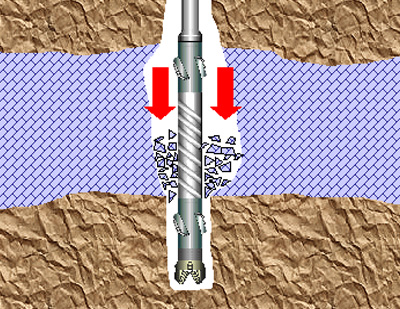
Some problems in rotary drilling are minor and others are serious and can result in failure to complete a hole or even loss of equipment. Many serious problems start minor but can become serious if not recognized or handled properly.

For example, in a loose sand zone, the borehole walls can casts of particles and cause drilling fluid loss. By reducing or increasing fluid velocity, you can stabilize the wall and regain fluid circulation. However, if you do not recognize the condition and you continue drilling, the wall will casts of particles  and create a cavity. The cuttings lose velocity, become suspended in the cavity, and tend to fall back into the hole when you add a drill pipe. This action can result in the drill pipe or the bit becoming stuck in the hole.

Lost Circulation

Lost circulation refers to a loss in volume of drilling fluid returning to the surface. The implication is that some fluid pumped down the drill pipe is entering the formations. The mud pit will lower, since some of the mud is used in forming a mud cake on the borehole wall; however, increased lowering can indicate circulation loss.

Causes

  • Losses can occur through open-graded sand or gravel or open joints in rock or when we drill in highly porous & permeable formation. .
  • A loss can occur when cuttings are not washed out and the borehole annulus becomes restricted, resulting in increased down-hole pressure.
  • Spudding also known as surge and swab (raising and lowering the drill string) the hole too violently can cause loss. Spudding helps wash cuttings, but down-hole pressures increase momentarily. Experienced drillers can estimate when spudding is safe.
  • Low formation pore pressure
  • Poor drilling fluid characteristic
  • Induced fracturing of formation from from excessive mud weight
  • Natural fractures or formation cracks
Surge Pressure

Solutions

Re-establishing circulation can involve several techniques:

  • Mud pressure (Pm) > formation pressure (Pf) – Decrease mud weight
  • You can add commercial items such as chopped paper, straw, cottonseed, and nut hulls to the mud pit.
  • Squeeze or grout cementing (Sometimes, while the loss zone is grouted and re-drilled, the grout is lost into the formation. In this situation, use the following step
  • Set casing through the loss zone.

Fall-In or Cavings

Fall-in is material that accumulates in the bottom of the borehole after you stop circulation. This material is borehole-wall material that results from, sloughing caving or cuttings previously carried in suspension.

Causes

  • Fall-in or caving occurs when you encounter a loose, unstable formation and the drilling-fluid weight is insufficient to stabilize the formation.
  • If mud cake is not formed properly → water from mud goes in → water comes in contact with clay/shale → hydration → so size increases → but there is no space to accommodate this: Weight cannot be supported and this bulge breaks from inside → Slowly this caving keeps on increasing.
Shale Swelling
Shale Sloughing

Shale Sloughing

This is Shale erosion due to Annular Turbulence Caused when a heavy weighted drilling fluid flows at a high speed inside the borehole and creates turbulence leading to sloughing of shale in unconsolidated formations

Solutions

  • If you anticipate or suspect fall-in, raise the drill bit off the bottom of the hole (20-foot minimum) each time drilling is interrupted. This will prevent the cuttings and fall-in from settling back around the bit until the problem is solved.
  • Good quality mud should be made so that an impermeable mud cake gets formed. i.e. add 1.1% – 4% CMC or mud extenders.

Stuck Drill String

The drill bit and any collars just above the bit are larger in diameter than the drill pipe. The string becomes stuck when cuttings collect on the bit and collar shoulder. This condition is called sanded in.

Drill String Stuck-up Indication

  • Cannot pickup the pipe
  • Pipe movement in the upward/downward is restricted but free circulation is easily be established.

Causes

  • Differential pressure sticking (High pressure of mud)
  • Formation of adhesiveness & thick Filter Cake → deposited after circulation stops (while pipe still on bottom)
  • Caving-in and crumbling of rocks
  • Substantial water loss

Mechanical Sticking

Conditions:

  • Drill cuttings, sloughing formations, shale deformation/cracks and salt flow pack off the annular space around the drill string.
  • A drill string is run too fast, such that it hits a bridge or a tight spot or the bottom of the hole
Mechanical Sticking

Mechanical Sticking – Shale Crack

Caused when filtrate from a water based mud enters the cracks present in the walls of the formation and cause swelling of the sensitive clays.

Shale Cracks

Mechanical Sticking – Settled Cuttings

Causes: Low annular velocity and/or poor mud properties. Drill cuttings settle on the low side forming a cutting bed.

Settle Cuttings

Preventive measures for Stuck Drill String

  • Limit Differential Pressure → Use Minimum Mud Weight Required to  Control Formation Pressures.
  • Reduce Contact Area (Use Low Solid Mud, Use Spiral Drill Collars, Use Centralizers/Stabilizers on pipes and casing,
  • Reduce Friction Factor (Control Water Loss, Use Filtrate loss Controller, Use Lubricants, Emulsions)
  • Reduce static time → Periodically Establish Circulation while Running Casing or Drill pipe in Deep Hole

Solutions

  • Wash a small pipe down the annulus to the bit and jet the settled sand back into suspension. When the annulus is too small to pass a jet pipe, a part of the drill string may be lost.
  • Erode Mud Filter Cake – at High Fluid Velocity (speed up pumps) – When the annulus is small, excessive up-hole velocity can promote erosion of the filter cake in granular zones and allow caving against the drill pipe. If this occurs, try to maintain circulation and rotation, even if circulation is slight.
  • With smooth pipe (not upset), hammering up and down will sometimes dislodge the string. You can reestablish circulation and continue drilling – Be careful because hammering up and down can produce unfavorable compacting of the sand. In a hole of fine-grained soil or shale, where the alignment has significantly deviated and the drill pipe has wallowed into the wall, the pipe can become wall stuck. Pipe friction and relatively high borehole pressure can move the pipe tighter into the wallowed groove as you pull the string. An alert driller should recognize early stages of deviation and take measures to realign the hole.
  • Spot Special Fluid; Oil, Acid.
  • Reduce Mud Weight as Far as Possible.
  • Rotate Pipe – Keep Moving Pipe.
  • If circulation cannot be established: Cut pipe or Unscrew Joint – If possible fish out drill string.

Drill String Failure

When the drill string parts, leaving a portion in the borehole, the drill string is rung off. The portion in the borehole is a fish and attempts to retrieve the portion is fishing. Fishing tools include a tapered tap and an overshot die (see fig. below)

Ringing off is normally fatigue failure in the drill-rod joints caused by excessive torque or thrust (repeated flexing and vibration that crystallizes heat-treated tool joints) or by borehole deviation (with flexing of the string). Examine drill rods for signs of failure.

Basket Graple Overshot
Spear Fishing tool

Deviation

A deviated borehole is called going crooked. If you make the initial setup without plumbing the Kelly, you can expect the borehole to go crooked. A crooked borehole usually amplifies other problems and can make a borehole unsuitable for a well. You should always anticipate deviation, since the borehole naturally tends to spiral from bit rotation. Variations in the formation badness may start deviation. Excessive bit load magnifies minor initial deviation. Use all available guides and collars and a reduction in bit load to minimize deviation.

Swelling Soil

The in-hole effects of swelling soil (shale or clay) that absorbs water from the drilling fluid is squeezing. The result is a borehole that is under-gauged to the extent that you cannot pull the bit by normal hoisting methods. In such cases, you can cut back through the blockage with a roller rock-bit or a drag bit. Swelling can cause caving and failure of the wall. Keep water out of the formation to prevent swelling. Special polymer drilling fluid additives that limit water absorption are available. High quality bentonite forms a thin but highly impermeable filter cake.

Under-gauged by Shale swelling

Talk to us for your upcoming Water Borehole Rotary Drilling Project

Geodata Evaluation & Drilling LTD. offers water borehole drilling services. Let us handle the project for you. contact us at www.geodatadrilling.com Phone: +234 8037055441

How to Interpret Water Borehole Pumping Test

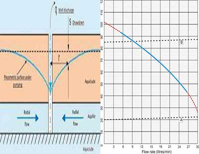
There are several ways of analyzing pumping test data, (The table below show the commonly used methods for pumping-test data analysis).

SNType of Aquifer Type of Pumping test data Names of methods
1Confine Aquifer I. Time Drawdown
data


II. Unsteady distance drawdown data


III. Quasi-Steady/ Steady Distance drawdown
data

IV. Recovery Data:

– Time Residual Drawdown data

– Time Recovery Data
– Theis Type curve method
– Cooper-Jacob Straight line method


Cooper-Jacob Straight line method


– Thiem method
– Graphical method


– Residual Drawdown-Time Ratio method
– Cooper-Jacob Straight line method
2Unconfined Aquifer without Delayed Yield I. Time Drawdown
data


II. Unsteady distance drawdown data


III. Quasi-Steady/ Steady Distance drawdown
data

IV. Recovery Data:

– Time Residual Drawdown data

– Time Recovery Data
– Theis Type curve method
– Cooper-Jacob Straight line method


Cooper-Jacob Straight line method


– Thiem method
– Graphical method


– Residual Drawdown-Time Ratio method

– Cooper-Jacob Straight line method
3 Unconfined Aquifer with Delayed Yield

I. Time Drawdown
data


II. Quasi-Steady/ Steady Distance drawdown
data
– Type-Curve method
– Newman Straight Line method


– Thiem method
– Graphical method
4Leaky Confined Aquifer without Storage in Aquitards I. Time Drawdown
data


II. Quasi-Steady/ Steady Distance drawdown
data
– Walton Type curve method
– Hantush Inflection Point method

– Type-Curve method
5 Leaky Confined Aquifer with Storage in Aquitards

I. Time Drawdown
data


II. Quasi-Steady/ Steady Distance drawdown
data
– Hantush Type Curve method


– Type-Curve method
Commonly used methods for pumping-test data analysis.

Some of these methods are quite sophisticated. However, for the purpose of this guidance note, what is important to the Supervisor is whether the borehole will deliver the required amount of water for the required pumping duration or not. The specific capacity of the borehole, which expresses the relationship between the yield and the drawdown, is the most important quantity of pumping test. (Step Test, Constant Rate Discharge Test and Recovery Test).

Specific Capacity=yield /drawdown (m3/hr. per meter drawdown)

By calculating the drawdown incurred by different pumping rates, and comparing that drawdown to the available vertical interval between the rest water level and the top of the well-screen (while allowing for likely seasonal water level variations, the effects of extended dry periods, and the interval occupied by the pump itself) it is relatively easy to determine a viable discharge for the well and whether the borehole can deliver sufficient water.

Calculation of Water Borehole Specific Capacity

  A pumping test was run for 24hours with a yield of (2,500 m3/hr.) and the drawdown (21 meter) were measured. The Specific Capacity is calculated as 2,500 m3/hr. divided by 21 meter, or 119 m3/hr. per meter
Borehole Specific Capacity

The Specific Capacity obtained just after a well is drilled and properly developed is typically the highest value that will be produced and is the benchmark with which to compare all future values. As time goes by, the Specific Capacity will decline as plugging of the well’s perforations or filter pack occurs, as the pump starts to fail, or as static water levels change.

Specific Capacity tests should be performed at least semi-annually and water levels (static and pumping) should be collected monthly to provide early detection of potential well problems. Rehabilitation work should be initiated when a well’s Specific Capacity drops by 25% (Driscoll, 1986).

Specific capacity can also be used to provide the design pumping rate or maximum yield for the well as follows:

Calculation of Water Borehole Maximum Yield

  For example, the specific capacity of a borehole is 27 m3/hr. Assuming that only 15 m of drawdown is available in the well, the maximum yield is calculated as the Specific Capacity times the maximum drawdown, or 27 m3/hr * 15 m, = 405 m3/hr. This should be verified with other pumping test method.  
Maximum Yield or Design Pumping Rate of Water Borehole

Calculation to determine if the borehole maximum specific capacity is enough to meet the need of the population end user.

As previously mentioned, the most important result of pumping test is to determine that the borehole flow for the required pumping duration is sufficient to meet the daily need of the population (maximum exploitable flow):

  • Less than 14 hours in operation, the borehole is sufficient to meet the need of the population.
  • Between 14 hours and 18 hours operation, bear in mind that the borehole may become too small in the near future due to population growth or reduced water levels in the aquifer due to prolonged exploitation. Furthermore, using the borehole becomes more expensive.
  • Over 18 hours operation. The borehole does not meet the needs of the population. Depending on the circumstances, you can decide whether or not to equip the bore or drill another borehole. (Arnalich-water and habitat 2011).
Calculation example: A borehole has been drilled for semi-urban population of 8000 people. The pumping test reveals that the maximum capacity of the borehole is 11 l/s. Is this enough to meet the needs of the population assuming 100 liters per person per day?

With a daily demand of 100 liters per person, the quantity of water consumed is: 8,000 people * 100 l/person* day = 800,000 liters daily demand.

The hourly production is: 11 l/s * 3600 s/hour = 39,600 l/hr

The required number of operating hours is 800,000 l / 39,600 l/hr = 20.2 hours.

The borehole is too small to meet the needs of the population.
Borehole maximum specific capacity and end users

Approximate Calculation of Operating cost

Given a certain maximum capacity of the borehole, you can calculate operating cost.

The main expense is derived from energy consumption. To determine whether the population is able to pay for the operating cost of the borehole, calculating the energy consumption cost is usually sufficient.

e = mgh/3.6 ∗ 10⁶ η ∗ cost rate per kWh for local electricity tariff

Where:

m = mass of water per day in kg (1 liter of water weighs 1kg)

h = the pumping height taken from the lowest drawdown point to the water      surface at the point of delivery.

g = gravity of acceleration on the surface of the earth at sea level is 9.8 m/s2

η = total efficiency for the pump, around 60% (for frictional losses use value of 0.5 (50%).

As generator are frequently required, you need to know the unit fuel cost of the diesel. The average fuel consumption of a generator is 0.3 liters of diesel per kwh produced.

  Calculation example: A borehole powered by a generator pumps 60,000 liters per day to a tank with a tank stand situated at elevation of 35m. The dynamic height of the borehole is 44m and the cost of diesel is #250 per liter. How much will it cost to pump a day?  

The pumping height is 35m + 44m = 79m.

The energy consumed is:  

e = mgh/3.6 ∗ 10⁶ η  = 60000 ∗ 79m ∗ 9.8m/ s² / 3.6 ∗ 10⁶ ∗ 0.5 = 25.8 kwh

The number of liters of diesel required is: 25.8 kwh * 0.3 liters diesel / kwh = 7.74 liters

The daily cost for the local population is: 7.74 liters * #250 /liter = #1,935
Operating cost and energy consumption

Water Borehole Transmissivity and Storage Coefficient

Data from constant-rate tests can be analyzed to derive the transmissivity of the aquifer. The storage coefficient of the aquifer can be calculated only if data from observation boreholes are available.

The goal of a recovery test, as in any aquifer test, is to estimate hydraulic properties of an aquifer system such as transmissivity, hydraulic conductivity and storativity (storage coefficient). One typically measures recovery after the termination of a constant-rate or step-drawdown pumping test to provide additional data for estimating aquifer properties.

  If transmissivity value of 10 m2/day is calculated from pumping test analysis, the question is, what does that value mean? Is a value of 10 m2/day good or bad?  
Transmissivity Interpretation

The answer mainly depends on what the intended yield of the borehole is. MacDonald et al (2005) carried out modelling using typical assumptions and parameters applicable to emerging countries, and came to the conclusion that for a borehole supplying 5,000 litres per day (20 litres per person for 250 people), the transmissivity value of the aquifer should be at least 1 m2/day.

An aquifer with a transmissivity value of 10 m2/day would be capable of yielding around 40,000 litres per day. By comparison, a public water-supply borehole in a typical sandstone aquifer capable of yielding about two million litres per day would have a transmissivity value of 300 to 400 m2/day when tested. Highly productive aquifers, capable of supporting major abstractions, can have transmissivity values of 1,000 to 2,000 m2/day.

Talk to us for your upcoming Water Borehole Pumping Test Project

Geodata Evaluation & Drilling LTD. offers water borehole pumping test services. Let us handle the project for you. contact us at www.geodatadrilling.com Phone: +234 8037055441

How to Perform Water Borehole Pumping Test

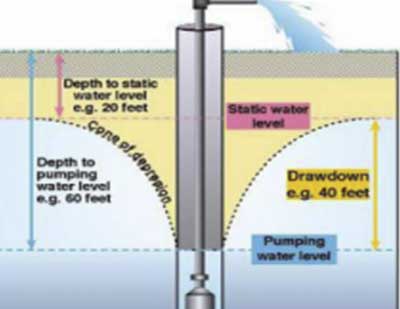
Pumping tests or aquifer performance tests is a field experiment in which a well is pumped at a controlled rate and water-level response (drawdown) is measured in one or more surrounding observation wells and optionally in the pumped well (control well) itself. The way in which the water levels respond to the pumping is then analyzed to derive information about the performance characteristics of the borehole and the hydraulic properties of the aquifer.

The Purpose of Pumping Test

Pumping tests can be undertaken for a wide variety of reasons, including the following:

  • To determine the reliable long-term yield (or ‘safe’ yield) of a borehole, and therefore whether or not the borehole can be regarded as a ‘success,’ and how many people it will be able to supply.
  • To assess the hydraulic performance of a borehole, usually in terms of its yield-drawdown characteristics. How much drawdown does it take to yield a certain amount of water?
  • To derive the hydraulic properties of the aquifer, such as transmissivity and the storage coefficient, or to reveal the presence of any hydraulic boundaries.
  • To test the operation of the pumping and monitoring equipment, to make sure that everything is working safely and efficiently, and if applicable, to confirm that the contractors have done their job properly.
  • To determine the effects of water abstraction on neighboring abstractions.
  •  To determine the environmental impact of the abstraction. All groundwater abstraction eventually has an impact; it is only a matter of where, when and whether or not the impact is acceptable.
  • To provide information on water quality. Is the water quality suitable for the intended use? Is it stable in the long term? Are there likely to be any problems such as drawing in saline or polluted water after extended periods of pumping?
  • To optimize operational pumping regimes (especially from multiple-borehole sources), including selecting the most suitable pumping plant for long-term use, and estimating probable pumping and/or treatment costs.

Preparation for Pumping Test

Before commencing any pumping test, there are certain basic preparations that should be made. These include:

  • Information about the borehole or well that is about to be tested.
  • The geological characteristics of the subsurface i.e., all those lithological, stratigraphic, and structural features that may influence the flow of groundwater.
  • The type of aquifer and confining beds.
  • The thickness and lateral extent of the aquifer and confining beds:
  • The aquifer may be bounded laterally by barrier boundaries of impermeable material (e.g., the bedrock sides of a buried valley, a fault, or simply lateral changes in the lithology of the aquifer material);
  • Any lateral recharge boundaries (e.g., where the aquifer is in direct hydraulic contact with a deeply incised perennial river or canal, a lake, or the ocean) or any horizontal recharge boundaries (e.g., where percolating rain or irrigation water causes the water table of an unconfined aquifer to rise, or where an aquitard leaks and recharges the aquifer);
  • Data on the groundwater-flow system: horizontal or vertical flow of groundwater, water table gradients, and regional trends in groundwater levels;
  • Any existing wells in the area. From the logs of these wells, it may be possible to derive approximate values of the aquifer’s transmissivity and storativity and their spatial variation

Pumping test equipment

The basic equipment to measure the two parameters in pumping test (water level in the pumped borehole and the rate at which water is being pumped) are as follows:

Measuring Water Level

The most common methods of measuring water level are as follows:

Dipper

Dipper

The hand-held water level monitor, commonly known as a “dipper,” or M-scope is the most practical, robust and easily available method of monitoring water levels in boreholes and wells. The dipper probe is lowered down the borehole, and when it reaches the water surface, an electrical circuit is completed and a ‘bleep’ is heard. The water level is then read off a graduated tape in centimeters and should be converted to meters. See fig above.

Pressure Transducer for Water Level Measurement

The transducer is placed in a known position down the borehole (below the water level) and it measures the pressure at that point. This information can be used to deduce the height of the water above that point, and therefore the water level in the borehole.

Transducers (with built-in dataloggers) have an obvious advantage: they can be left unattended for long periods, while still taking frequent water-level readings.

Pressure Transducer

Tape Method

Use this method to measure the depth to the static level in a shallow well. Conduct this test as follows:

Chalk one end of a weighted steel tape with carpenter’s chalk. Lower the tape into the well to a depth of 1 or 2 feet past the chalk. (You can use soluble felt-tip markers as an alternative to chalk.) Measure the wetted length of the tape and subtract the amount from the total length lowered below the reference point to obtain the water depth. This test is accurate to within 0.01 foot.

Steel Tape

How to Measure Pumping Rate

The most common method of measuring pumping rate is as follows:

Measured-Container Method

You can determine the flow rate from a well or pump by measuring the time required to fill a container with a known volume. With this method, use small containers for early measurements and large containers for later measurements. Also, use an instrument, such as a stop watch, for accurate time measurements. Use the following equation:

where—

FR = flow rate, in GPM.

V = volume, in gallons.

T = time required to fill container, in seconds.

Flow-Meter Method

A turbine-type flow meter will give an acceptable flow-rate reading. This uses spring-loaded pistons that are deflected by the flow of water, and the flow rate is read off the graduated scales.

Flow Meter

Weir tanks

A weir tank is a thin-plate ‘V-notch’ gauging weir within a self-contained tank. Weir tanks must be installed exactly level, and there must be an accurate method of measuring the water level inside the tank, plus a conversion table supplied by the tank manufacturer (to convert the water levels into flow rates). See BS ISO 14686:2003 for more information about constructing and using weir tanks.

Alternatively, small weir tanks can be made using local materials, sometimes even a converted oil drum. These weir tanks should be calibrated by an independent flow-measurement method, in order to ensure reliable data. For accurate results, care should be taken to follow design advice (see BS ISO 14686:2003), especially about the thin-plate ‘V-notch’ itself.

Weir Tank

Whichever method is used, it is important to measure the pumping rate frequently during the test since it will probably fall as the water level drops, and an average pumping rate needs to be calculated for use in the test analysis.

Types of pumping test

There are different types of pumping test. Three main types of pumping test will be discussed for the purpose of this guidance note, namely:  Step test or variable discharge, Constant discharge test and Recovery test.

Step test

The step test (sometimes referred to as the step-drawdown test) is designed to establish the short-term relationship between yield and drawdown for the borehole being tested. It consists of pumping the borehole in a sequence of different pumping rates, for relatively short periods (the whole sequence can usually be completed in a day). There are many different ways to perform a step test, but the most common practice is as follows:

  • Start with a low pumping rate, and increase the rate with each successive step, without switching off the pump between steps.
  • Aim for four or five steps in total, with the pumping rates roughly spread equally between the minimum and maximum rates.
  • All steps should be of the same length in time, with somewhere between 60 and 120 minutes per step being common.
  • The pumping rate for the final step should be at or beyond the intended operational pumping rate when the borehole is fully commissioned. Of course, this depends on whether the pump being used for the step test is capable of that pumping rate.

Setting pumping rates

It is advisable to spend time, on the day before the step test itself, experimenting with the valve settings that are necessary to produce the required pumping rates for each step. Manually operated gate or globe valves are commonly used, and these are operated by a screw handle. Fully close the valve, then open it to the fully open position, counting the number of turns of the handle that are made between fully closed and fully open. Experiment with opening the valve different numbers of turns from the fully closed position, to achieve the different pumping rates for the steps, and make a note of the results.

Gate Valve in Discharge Pipe

Choosing step length

In practice, the length of each step depends on the number of steps and the total time available for the test (which is usually one day), but 60, 100 or 120 minutes are common step lengths. Ideally, the water level in the borehole will approach equilibrium at the end of each step, but this cannot always be achieved. Even if the water level has not reached equilibrium at the end of each step (in other words, if it is still falling slowly), the results from the test will still be useful. They provide a ‘snapshot’ of borehole performance under certain conditions, and can be compared with the results from the same test (same pumping rates and step length) repeated at another time, to see if the borehole performance has changed. If at the end of the planned time for the first step the water level is still falling quickly, the decision may be taken to extend the length of the step (and extend the length of subsequent steps to match). Further details on the theory and practice of step tests can be found in Clark (1977).

Step-test procedure

Assuming that all the equipment is ready and people have been assigned their tasks, the procedure for conducting a step test is as follows:

  1. Choose a suitable local datum (such as the top of the casing) from which all water-level readings will be taken, and measure the rest-water level. The water level must be at rest before the start of the test, so the test should not be conducted on a day when the borehole is being drilled or developed, or when the equipment is being tested.
  2. Open the valve to the setting for the first step (determined by prior experiment, as described above) and switch the pump on, starting the stopwatch at the same time. Do not keep changing the valve setting to achieve a particular pumping rate (a round number in litres per minute, for example). Rather, aim for an approximate rate and measure the actual rate (see 4) below).
  3. Measure the water level in the borehole every 30 seconds for the first 10 minutes, then every minute until 30 minutes have elapsed, then every 5 minutes until the end of the step (the length of each step having been decided during the test preparations). If you miss the planned time for a water-level reading, write down the actual time the reading was taken. Record all the readings on the standard step-test form.
  4. Measure the pumping rate soon after the start of the step, and then at intervals during the step (every 15 minutes would be reasonable). If there is a noticeable change in the rate of increase of drawdown or the pump sounds different, then measure the pumping rate at those times as well. If the pumping rate changes significantly (say by more than 10%), then adjust the valve setting to maintain as steady a pumping rate as possible throughout the step. Be careful not to over- adjust and make the problem worse.
  5. At the end of Step 1, open the valve further, to the setting for Step 2, note the time (or restart the stopwatch) and repeat the procedures for measuring water levels and pumping rates (see 3) and 4) above).
  6. Repeat the procedure for subsequent steps, progressively increasing the pumping rate for each step.
  7. At the end of the final step (which will probably be Step 4 or 5), switch the pump off, note the time (or restart the stopwatch), and measure the water-level recovery at the same measurement intervals as for measuring the drawdown in each step. Continue for at least the length of a step, and ideally for much longer, until the water level approaches the pre-test level. See Chapter 6 for a full explanation of the recovery period.

Constant Rate discharge

The constant-rate test is the most common type of pumping test performed, and its concept is very simple:

The borehole is pumped at a constant rate for an extended period (from several hours to several days or even weeks) while the water levels and pumping rates are monitored.

If the most value is to be gained from constant-rate tests, water levels should be monitored in an observation borehole as well as in the pumping borehole (or better still, several observation boreholes at different distances from the pumping borehole).

The present guidelines concentrate on what to do with the data obtained from the pumping well alone. Data from constant-rate tests can be analyzed to derive the transmissivity of the aquifer. The storage coefficient of the aquifer can be calculated only if data from observation boreholes are available. (Which is assumed not to be the case here).

Observation wells are necessary in order to determine fully the aquifer properties. Table below gives guidance on the minimum durations that should be allowed for constant discharge tests.

Discharge rate m3/dayMinimum duration of constant discharge days (of constant 24 h discharge)
Up to 5001
500 to 1 0002
1 000 to 3 0004
3 000 to 5 0007
Over 5 00010
Minimum Duration of Constant discharge Test

In certain situations, increases or decreases in these periods will be appropriate. Longer tests would be required for example to adequately assess the influence of boundaries. The effect of a recharge boundary is a slow-down (deceleration) in the rate of drawdown.

Where the recharge source is a specific feature, such as a watercourse or a lake, the time that elapses before the onset of this deceleration will increase in proportion to the square of the distance between the pumping well and the recharge source. Eventually, drawdown will stabilize for the remainder of the test.

If a delayed-yield effect occurs, the development of the time-drawdown relationship will be delayed. It is not possible to estimate accurately in advance the length of this delay unless it has occurred in nearby wells previously tested in the same aquifer. If a delayed yield is expected, an extension of the duration of the test should be considered.

Barrier boundaries have the effect of increasing the rate of drawdown and present a serious constraint on the yield of the well. The shorter periods given in Table below may therefore require extending by one or two days to observe the effects adequately, particularly if they appear towards the end of the period initially specified. (The pumping of another well in the same aquifer will have the same effect as a boundary, if the cones of influence of the two wells intersect).

 The two main decisions to make with a constant-rate test are the pumping rate and the length of the test:

Pumping  rate

Typically,  the  chosen  pumping  rate  is equal to the intended operational pumping rate when the borehole is fully commissioned, although some hydrogeologists  prefer  to  set  the  test  pumping  rate 25-50% higher than the intended operational pumping rate. Information from a step test is very helpful in  deciding  this  pumping  rate.

The chosen rate  also depends on how the borehole is going to be operated. Some boreholes are pumped at a high rate to fill up a storage tank or reservoir in a relatively short period, and then the water is used gradually (by gravity) from storage. The pumping rate for the test can either be the actual pumping rate when the pump is switched on, or the average long-term pumping rate (including the operational non-pumping periods). If the focus of the test is on long-term sustainability, then it would be better to use the average pumping rate.

Length of test

Ideally, a constant-rate test should be long enough for the water level to reach or at least approach equilibrium.  How long  it  takes  to  do  this depends on the hydraulic properties of the aquifer. Again, the step-test results will help in understanding how the aquifer responds to pumping. For a small or medium borehole, one or two days should be sufficient, but for a large borehole expected to supply a large population, one or two weeks are common.

Many aquifers behave differently in the wet season compared with the dry season; if possible, constant-rate tests should therefore take place at the relevant time of year. For example, if the borehole is intended as a source of water for critical drought periods, then it should be tested during the dry season, otherwise a false impression will be gained of the aquifer’s performance. Another good reason to conduct a test during a dry period is that the groundwater levels may be influenced by recharge from heavy rainfall, which makes it more difficult to interpret the test results.

Maintaining a steady pumping rate during a constant- rate test is sometimes a problem, especially if the chosen pumping rate results in a large drawdown. This is because for  centrifugal  pumps  (the  most  commonly  used  type of pump) there is a relationship between pumping rate and pumping head. Incidentally, the pump must be set at a depth that is several meters below the deepest water level expected during the test.

Constant-rate Test Procedure

Assuming that all the equipment is ready and people have been assigned their tasks, the procedure for conducting a constant-rate test is as follows:

  1. Choose a suitable local datum (such as the top of the casing) from which all water-level readings will be taken, and measure the rest-water level. The water level must be at rest before the start of the test, so the test should not be conducted on a day when the borehole is being drilled or developed.
  2. Open the valve to the appropriate setting and switch the pump on, starting the stopwatch at the same time. Do not keep changing the valve setting to achieve a particular pumping rate (a round number in liters per minute, for example). Rather, aim for an approximate rate and measure the actual rate.
  3. Measure the water level in the borehole every 30 seconds for the first 10 minutes, then every minute until 30 minutes have elapsed, then every 5 minutes until 2 hours have elapsed. After 2 hours, observe how quickly the water level is still falling, and decide an appropriate frequency for water-level readings until the end of the test. If the water level is falling very slowly, then a reading every 30 minutes or even every hour may be sufficient. If the test is to continue for several days, review the measurement frequency depending on the behavior of the water level. If you miss the planned time for a water-level reading, write down the actual time the reading was taken. Record all the readings on the standard form.
  4. Measure the pumping rate soon after the start of the test, and then at intervals during the test (every 15 minutes would be reasonable for the first few hours, then decide a suitable frequency for the remainder of the test). If there is a noticeable change in the rate of increase of drawdown, or if the pump sounds different, then measure the pumping rate at those times as well. If the pumping rate changes significantly (say by more than 10%), then adjust the valve setting to maintain as steady a pumping rate as possible throughout the test, but be careful not to over-adjust and make the problem worse.
  5. At the end of the test, switch the pump off, note the time (or restart the stopwatch), and measure the water- level recovery at the same measurement intervals as for measuring the drawdown. Continue until the water level has  recovered  to  the  pre-test level, or at least approaches that level. See the next chapter for a full explanation of the recovery period.

If there is a problem during the test, such as an interruption to the power supply or a pump failure, then use your judgement, depending on when the problem occurs and how long it is likely to last. For example, if something goes wrong in the first few minutes, wait for the water level to recover and start again. If the failure occurs well into the test and can be solved quickly, just restart the pump and carry on. If it is going to take a long time to solve, it may be better to allow full recovery of the water level and start again. For long constant-rate tests, it is especially important to ensure that there is an adequate fuel supply to last the planned duration of the test.

Recovery Test

The recovery test is not strictly a pumping test, because it involves monitoring the recovery of the water level after the pump has been switched off in step tests and constant-rate tests. Recovery tests are valuable for several reasons:

  • They provide a useful check on the aquifer characteristics derived from pumping tests, for very little extra effort – just extending the monitoring period after the pump has been switched off.
  • The start of the test is relatively ‘clean.’ In practice, the start of a constant-rate test, for example, rarely achieves a clean jump from no pumping to the chosen pumping rate. Switching a pump off is usually much easier than starting a pump, and the jump from a constant pumping rate to no pumping can be achieved fairly cleanly.
  • Similarly, recovery smooth out small changes in the pumping rate that occurred during the pumping phase, and there is no problem with well losses from turbulent flow. This results in more reliable estimates of aquifer properties when the recovery data are analyzed.
  • The water levels in the borehole are easier to measure accurately in the absence of turbulence caused by the pumping (especially in the early stages of the test, when water levels are changing quickly). Some people find that it is easier to take readings quickly with a dipper when the water level is rising than when it is falling.
  • Recovery tests represent a good option for testing operational boreholes that have already been pumping at a constant rate for extended periods. In these cases, the recovery test can be performed when the pumps are first switched off, followed by a constant discharge test when the pumps are switched back on again.

Ideally, the duration of the recovery test should be as long as is necessary for the water to return to its original level, which, theoretically, would be as long as the duration of the pumping phase of the test program. In practice, however, the recovery test is often shorter, partly for reasons of cost (keeping equipment and personnel on the site). It should not be too short however, because as described in relation to the constant-rate test, the data from the early part of the test are affected by well storage. If the data from the constant-rate test have been roughly plotted in the field on semi-log graph paper, this will give some idea of the length of time before the data become useful for calculating transmissivity (when they fall on a straight line).

The pump should not be removed from the borehole while the recovery test is taking place, because the sudden removal of the submerged volume of the pump and rising main will cause a sudden change in the water level in the borehole. For a similar reason, there must be a non-return valve (called a foot-valve in this context) at the base of the rising main. In the absence of a foot-valve, when the pump is switched off, the contents of the rising main will flow back down into the borehole and cause a sudden change in the water level in the borehole. Having said that, unless the foot-valve can be opened from the surface, the rising main will be full of water, and therefore heavy, when it is removed from the borehole. Thus, it may not always be practicable to carry out a recovery test.

Recovery Test Procedure

The procedure for undertaking a recovery test is as follows:

  1. Switch the pump off and start the stopwatch at the same time.
  2. Measure the water level in the borehole in the same way as for the start of the pumping test, that is, every 30 seconds for the first 10 minutes, then every minute until 30 minutes have elapsed, then every 5 minutes until 2 hours have elapsed. After 2 hours, observe how quickly the water level is still rising, and decide an appropriate frequency for water-level readings until the end of the test. If the water level is rising very slowly, then a reading every 30 minutes or even every hour may be sufficient. If you miss the planned time for a water-level reading, write down the actual time the reading was taken. Record all the readings on the standard form. Make sure the same datum is used for measuring water levels as for the pumping phase.

Talk to us for your upcoming Water Borehole Pumping Test Project

Geodata Evaluation & Drilling LTD. offers water borehole pumping test services. Let us handle the project for you. contact us at www.geodatadrilling.com Phone: +234 8037055441

How to Drill and Construct Deep Water Borehole

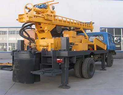
After Drill-Rig Setup, connect the discharge piping. Depending on the type of drilling operation, connect either the air compressor or the mud pump to the standpipe on the mast.

Compressor and mud pump on a Rotary Rig
  • Install or dig a mud pit, whichever is applicable. Make the appropriate connections to the mud pump to ensure continuous circulation of the drilling fluid.
  • If you use rotary drilling with mud, connect or place the suction line of the mud pump in the mud pit and fill the pit with water. Close the standpipe valve and prime the mud pump. Mix the drilling fluid in the mud pit by slowly circulating fluid through the mud pump.
Portable Mud Pit
Suction line connected to Mud Pit

Before you start drilling, you must select a drill bit. Consider the well diameter and the type of formations you will drill through.

The types of bits are Drag bits: Use for soil, unconsolidated materials usually found near the surface. Tricone roller-rock bits. Use for a variety of materials from soft formations to hard rock. (The bits are available in different degrees of hardness).

Tricone roller-rock bit
Drag bit

Starting the Drilling Operation

The first operation is spudding in (starting the borehole).

Rotary Table Kelly Drive

Drive Mechanism for Rotary Rigs

The drive mechanism for drilling operation is provided either at the rotary table Kelly drive (table drive) or at the swivel (top head drive).

On rotary rigs with top head drive mechanism, the bit with drill collar and subsequent drill pipes are connected directly to the drive shaft of top head drive. This process facilitate fast drilling speed and short auxiliary time for drill pipe connection – Step 1 to Step 5 below are not applicable in top head drive rotary rigs.

Top Head Drive

Step 1. Make up the drill bit on the Kelly and lower the bit to the ground.

Step 2. When the bit contacts the ground, engage the rotary table and clutch to start drilling. (Ensure to start drilling in true vertical direction. Straightness is particularly important for water boreholes in which long strings of casing and screens may have to be installed with a gravel pack filter).

Step 3. After the borehole advances 6 to 12 inches, engage the mud pump to start circulating the drilling fluid (which will be mud or air).

Step 4. After drilling down the kelly, stop the rotation and raise the kelly about 4 inches off the bottom of the borehole. Circulate the drilling fluid until all drill cuttings are removed.

Step 5. Disengage the mud pump, raise the Kelly, and remove the bit.

Finishing the Operation

After spudding in, use the following steps to finish the operation:

Step 1. Makeup the bit on a drill collar. Suspend the collar and bit in the borehole using the hoist or sand line. Support the drill collar in the hole using slips.

Step 2. Clean and lubricate the threads on the Kelly bar and makeup the Kelly to the threads. (On top head drive rigs, you makeup the drill string to drive shaft of drive head).

Step 3. Remove the slips, and lower the kelly so that the drive bushing engages the rotary table and that the tool string is lowered to the bottom of the borehole.

Step 4. Engage the mud pump again and continue drilling. After drilling down the kelly, circulate the drilling fluid until the cuttings are removed. Raise the tool string until the tool joint is 4 to 6 inches above the rotary table.

Step 5. Disengage the mud pump and set the slips to support the tool string. Disconnect the kelly from the string and set the kelly back to the cradle position.

Step 6. Run out the sand line, remove the end cap, and connect a hoisting plug to another drill collar or to a joint of drill pipe.

Step 7. Lift the drill steel with the hoist line or sand line and place the hoisting plug on the drill steel

Step 8. Remove the lower end cap. Clean and lubricate the threads. Make up the threads to the string in the hole with pipe wrenches.

Step 9. Lift the entire string slightly and remove the slips. Lower the string until the tool joint is 4 to 6 inches above the rotary table and the slips are reset.

Step 10. Make up the kelly to the tool string, remove the slips, engage the mud pump, lower the string to the bottom of the borehole, and continue drilling. Repeat the process until you reach the desired depth.

Step 11. Reverse the process to come out of the borehole.

Reaming – After drilling a drill stand down, it is advisable to back ream and enlarge the existing hole.

Rotary Rig component

Installation of Surface Casing

If the borehole has a tendency to cave in during drilling (when drilling in loose, unconsolidated materials.)  install surface casing when drill to the desired depth.

When installing the casing before the well screen, such as surface casing, the casing must be larger than the screen. Therefore, use a larger drill bit than the one used to complete the screen portion of the borehole. The decision to use surface casing should be made before mobilizing and should be based on the geologic information about the site.

Connecting Elevator to Casing
Casing Slip

Use the following steps to install the surface casing:

Step 1. Drill the borehole to a predetermined depth, and remove all the cuttings by circulating the drilling fluid. Withdraw the drill string and remove the bit.

Step 2. Set the kelly back in the cradle. Connect the elevators to the first section of surface casing that is lifted over the borehole by using a casing elevator and the hoist or by using a sand line.

Step 3. Lower the casing into the well and set the slips, which suspend the casing in the well, in the spider bowl.

Step 4. Disconnect the elevator. Hoist the next casing section with the elevator, and place it in the first section. Join the two sections. Slightly lift the string of casing, and remove the elevator from the lower section. Lower the casing, and repeat the process until you reach the surface casing depth in the well.

Step 5. Grout the casing in place with a cement grout. After the grout sets (about 24 hours), resume drilling operations using a drill bit that will fit inside the surface casing. Drill the well to the desired depth, case and screen the lower section of the well using the single-string method. (With this method, you install the casing and screen (that have been joined) in a single assembly).

Borehole Cement Grout

Borehole logging

For a borehole to be properly logged, the driller and supervisor need to know its exact depth at all times. This is necessary for the calculation of drilling charges, and while designing the borehole. First, make a note of the length of the drill bit and of any other tools that may be used to drill the hole. Put the bit on the ground and make a chalk mark, ‘0,’ on the first drill pipe against a suitable fixed point on the rig and at a known height above ground level, such as the drilling table (which centralizes the drill pipes in the hole). From then on, marks can be made on the drill pipe at regular intervals – say, every half meter – to record the depth of drilling and to assist in the logging of penetration rates.

Formation Sampling

Formation samples need to be obtained as drilling proceeds: the usual sampling interval is one meter or every stand drilled. There will be a slight delay as formation fragments are lifted to the surface by the circulating mud, but ensure to make a rough estimate or calculation of the up-hole lag time and actual depth at which cuttings were derived. Cuttings obtained from the shallow mud channel near the borehole should be washed in water to remove mud, and laid out in order (by the depth at which each was acquired) on the ground or in a sample box with separate compartments for each sample. They can then be logged (Identification of lithology and description with respect to depth) by the supervisor or site geologist and bagged if required. Samples should, of course, be labelled correctly with all information relevant to the job in hand.

The main attributes of a borehole log are accuracy and consistency; a good set of logs can be a useful resource when planning future drilling programs. Drillers must keep their own logs and notes and, as is often stipulated in contracts, these should be accurate; however, in practice, they cannot always be relied upon, especially if the supervisor is absent from the site for a period.

All geological samples and water strikes should be logged by the drillers and the supervisor, as this important information will be required for designing the borehole and the equipment to be installed.

Full borehole logging may also include geophysical logging, which is normally carried out only after a well has been completed.

Drill Cuttings

Geophysical Logging

Information about structural features and geological formations in a borehole can be remotely obtained by geophysical borehole logging techniques. The object of well logging is to measure the properties of the undisturbed rocks and fluids they contain. Geophysical logs can provide information on lithology, the amount of water in a formation, formation density, zones of water inflow, water quality, and other in situ parameters that cannot be derived from highly disturbed drilling samples. A suite of geophysical log data, including deep-penetration methods, will more or less complete the technical description of a borehole, but geophysical logging is a specialized field best left to geophysical contractors or hydrogeological consultants. A logging unit consists of a power supply, a receiver/data processing unit, and a cable on a powered winch that lowers special sensor probes (‘sondes’) into the borehole to measure various properties. The cable contains multi-conductors that transmit signals to the receiver console. Data, processed by computer, can be shown as a geophysical record on a graphic display, which should consist of a number of different structural, formation, and fluid logs. Specialized software packages enable manipulation, interpretation, and comparison of data. Multiple-sonde geophysical (‘suite’) logging can provide a substantial amount of information about the sub-surface conditions in and around a borehole.

Geophysical Borehole logging Equipment

Casing and Screen Installation

You can use the following method to install screens:

Step 1. Place a casing section in the well. Cap the casing or the screen on the lower end so materials from the bottom of the well will not enter the well. (Depending on if the casing or screen is designed to install at the business end of the borehole (Total depth – TD)

Step 2. Suspend a screen section over the well and attach the screen section to the casing section.

Step 3. Lower the screen and casing section. Suspend them in the well either by the elevator resting on the rotary table or by slips in the spider bowl.

Step 4. Add casing until the screen reaches the desired depth.

Water Borehole Casing and Screen

Gravel Pack Filtering and Backfilling

The last procedure when installing screen and casing is to place a gravel-pack filter around the screen and backfill material around the casing. If you place the screen in material such as gravel or very coarse sand, you may not need a gravel pack. Place the gravel filter material around the outside of the casing. Deposit the material to the bottom of the well. Add gravel to about 5 feet from the top of the screen. (Use the sounding method to determine the level of the gravel.) Add impervious backfill around the casing from the gravel pack to about 10 to 20 feet from the surface. If you use grout instead of impervious material, add a couple of feet of clay above the gravel to prevent the grout from entering the gravel filter. Bring the grout to the surface.

Water Borehole Gravel pack

Well Development

Frequently, when a well is first installed, the efficiency (production per foot of drawdown) is not satisfactory, and you must develop the well either by pumping or surging or both. Developing a well removes the remaining drilling fluid, breaks down any filter cake buildup on the borehole wall, and flushes the fines in the formation (adjacent to the grovel pack) into the well. Make sure that you pump the well of all fine sediments and sand with an airlift before installing the submersible pump. If you do not, the pump and components will wear out prematurely. To develop a well, pump or blow the drilling fluid out of the well. Agitate the water in the well to produce an alternating in and out flow through the well screen (or gravel pack). There are several methods available to develop a well.

Water Borehole Development with Compressor

Sanitary Seals.

All wells must have a sanitary seal to prevent contamination from surface runoff. Mix cement grout and place it in the annulus between the well casing and the borehole wall.

Extend the grout from the surface to the top of the backfill material (30-foot minimum). You should also pour a concrete platform (about 4 feet by 4 feet) around the casing at the surface with the casing extended at least 1 foot above the surface. The upper surface of the slab and the surrounding area should be gently sloping away from the well for better drainage. In addition to a surface grouting, you need to install a well seal (a type of bushing or packing gland) to prevent foreign materials from entering the inside of the well casing. You normally install the well seal when you install the pump, which is after you complete all development, testing, and disinfecting.

Sanitary seal and Well head Protection

Pumping Tests

After installing a well, you should perform a pumping test. The test will show you if the well can produce the required amount of water. If the well is considered permanent, the pumping test should help you evaluate any future performance deterioration. Evaluation parameters are flow rate, time, and drawdown in the well.

Pumping Test Setup

Talk to us for your upcoming Deep Water Borehole Drilling Project

Geodata Evaluation & Drilling LTD. offers water borehole drilling services. Let us handle the project for you. contact us at www.geodatadrilling.com Phone: +234 8037055441

Manual Water Borehole Drilling Design and Construction

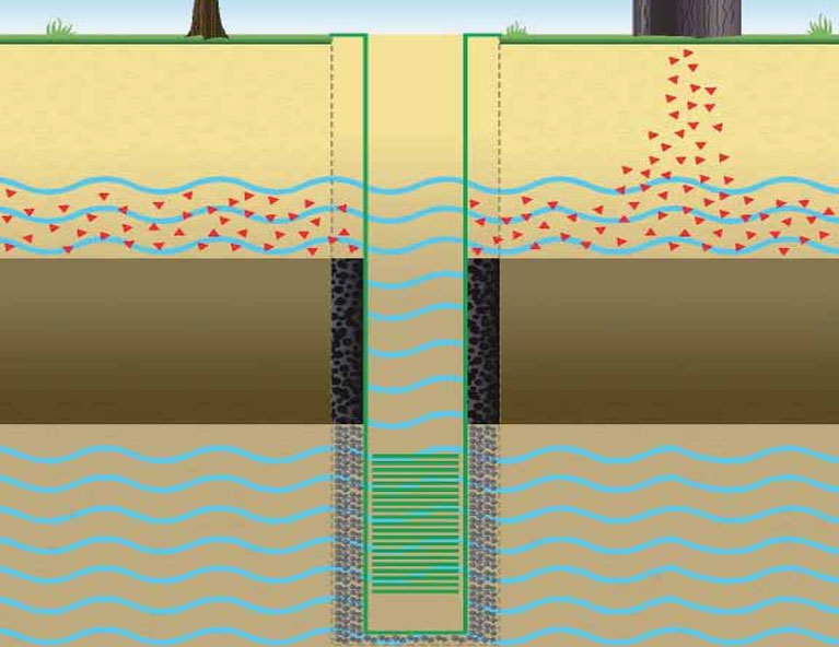
To achieve a good well design, a drilling log should be completed, a drilling log during the actual drilling process, from the drilling logs, the exact depth and length of the well screen, the depth and thickness of the gravel pack and sanitary seal can be determined.

Drilling log

Borehole diameter

The internal diameter of the PVC well casing is selected to fit the outer diameter of the pump that is going to be installed. The drilled diameter of the borehole in turn depends on the outer diameter of the PVC well casing. For the diameter of the borehole, it is important to realize the following:

The drilled diameter of the borehole should be at least 2-inch larger than the outer diameter of the PVC well casing to be able to place the gravel pack and sanitary seal. If this rule is not applied and the space between the PVC well casing and the borehole wall is too small, it is almost impossible to place the gravel pack and sanitary seal at the correct depth. Furthermore, the backfill may get ‘stuck’ on its way down (this is called ‘bridging’) and end up in the wrong position.

Borehole depth

When the final depth for the bottom of the well-screen in the aquifer is reached, an additional two meter should be drilled. This is to allow for fine soil particles, suspended (mixed with the water) in the borehole, to settle prior to and during the installation of the well-screen and casing, by doing so, the determined well-screen depth can be maintained, and to accommodate a sump.

Drilling the borehole to depth

Finally, before the drilling pipes are lifted, the fluid used to drill borehole should be flushed with clean water to remove all fine particles that are suspended in the hole. If this is not done, the particles will settle at the bottom of the well influencing the final installation depth or enter the well-screen during the installation of the well casing.

Materials: PVC well-screen and casing

Several different PVC pipes exist, varying from cheap drain pipes to expensive, high class, slotted well screens and casing pipes.

For a potable water well use by a single household or a few households a deeper hole may be needed. In this case a self-slotted 4-inch PVC pipe can be used.

In large water projects (for Governments or NGOs) for communal potable water wells, equipped with a high horse power submersible pump, a deeper hole is needed 5 to 6-inch standard factory slotted PVC well casing pipes are often required (to maximize yield, to ensure high construction quality, and to accommodate the pump). These wells will be significantly more expensive, but of better quality.

PVC Well screen and Casing

Slots are the openings in the well-screen which allow groundwater to flow into the well. In theory the slot size (width) should be smaller than the mean size of the soil particles. However, in some countries only 1 factory-made slot size (1mm) is available. For low-cost wells, one can make the slots by hand using a hacksaw.

Sump

To increase the lifetime of the well-screen, it is advised to attach a 1-meter sump at the bottom of the well-screen, into which any particles entering the well screen from the aquifer can settle, without blocking the well-screen and pump.

The sump simply consists of a 1-meter plain PVC pipe, which is closed at the bottom end. To close the bottom of the sump a factory-made wooden or PVC cap can be inserted. Alternatively, the bottom end of the sump pipe can also easily be closed by some cutting and bending. Make 4 cuts in the bottom part of the sump pipe and heat the pipe end. Fold the four parts inside and allow the parts to cool (see photo).

Sump

Alternatively cut out 6-8 triangular parts. The remaining parts can be bent together to a point. Making a point will reduce the risk of ‘scraping’ the borehole wall when the well-screen is lowered into the borehole. To completely seal the bottom of the sump 10 cm of cement mortar should be poured in the sump.

Pipe joints

Casing and well-screen pipes are usually joined by glued sockets. The more expensive purpose-made casings and well-screens with a wall thickness of at least 5 mm are threaded. When the pipes are glued together, it is very important to clean and roughen both ends, the inside of the socket and the outside of the pipe to be glued. Then, put sufficient glue all around on both ends and put the pipes together in one move.

PVC Pipe: Threaded and Socket type

Gravel pack

The gravel pack fills the space between the aquifer (sand particles) and the well screen preventing the wall of the hole from collapsing on to the well-screen and may serve to filter some of the fine sand particles from entering the well.

The gravel should consist of a grain size (generally 1.5 – 3mm) which is just larger than, and no more than twice to three times, the slot size of the well-screen. Good size gravel looks more like coarse sand, rather than gravel. The grains are best when round in shape. Such material can often be found on river beds or lake shores. The best way to prepare suitable gravel is using maximum and minimum sized sieves (grains which are too small or too big are sieved out).

Gravel pack

Sanitary seal

It is essential to install a sanitary seal if the well needs to yield good quality water. The sanitary seal can consist of cement-water mixture (cement grout).

The water and cement are mixed until a thick slurry is created (26 liters of water to one 50 kg bag of cement will make about 33 liters of cement grout). If cement grout is used as a sanitary seal, first a half meter of clay should be back filled on top of the gravel pack to prevent the grout from penetrating the gravel pack.

Sanitary seal

Water Borehole Construction

Step 1, Preparations

Prepare all materials needed for the installation and backfilling. Measure out the effective length of the PVC pipes and cut the last pipe to a length, allowing 1 meter to be left above ground level, after installation. Number the pipes in order of installation.

Centralization of the well screen

To prevent the slots from becoming blocked with clay due to scraping of the well screen against the borehole wall during installation, the well-screen should be centralized. Centralizing the well-screen in the borehole also allows the gravel pack to settle equally around the screen, leaving at least 1-inch of gravel all around the well-screen. Centralization can be achieved by attaching spacer rings or centralizers with an interval of every 3 meter around the well-screen. The spacer rings can be made of PVC rings, which can be attached on 4 sides around the well

Step 2, Installation of the PVC pipes

A practical method of lowering the PVC pipes into the borehole is to use a rope (see picture). One end of the rope is attached to the drill rig and the other end is wrapped three times around the pipe to form a self-closing loop. The rope is used to prevent the casing and screen slipping into the borehole while adding a new length of pipe. Install all the prepared pipes, and leave 1 meter (see step 1) of pipe above ground level so that the well-screen is placed at the correct depth.

Casing Installation

Step 3, Cleaning and flushing the well-screen

When the well-screen has been installed at the correct depth, the pipes and screen should be flushed in the case of fluid drilled boreholes. Pour water into the PVC pipes and allow the dirty water to overflow out of the borehole. If the added water only enters the well slowly (or not at all), this could indicate blockage of the well-screen slots by clay or fine material from the borehole wall. Extra water pressure in the casing and well-screen should then be created by adding a plunger or surge block (or simply a plug of cloth), which is then moved up and down in the casing. Repeat this process until the water directly flows away when added. Continue flushing with clean water until the water which is coming out of the borehole is clean. Only then the gravel pack should be installed.

Cleaning Screens

Step 4, Installation of the gravel pack

The gravel pack is now poured in the annular space around the pipe. At the same time the PVC pipe is moved from side to side to guarantee an easy passage for the gravel down to the screen. Pour in the gravel slowly, to prevent bridging (gravel getting stuck at the wrong level). Use the measurement tape or tool to measure the depth to the top of the gravel and fill to 1-2 meter above the top of the well-screen.

In fluid drilled holes, water will overflow from the PVC casing pipe, as the gravel is dropped around the well-screen. Water will stop overflowing the PVC casing pipe when the entire length of the well-screen has been backfilled.

Gravel Pack Installation

Step 5, Installation of the sanitary seal

When the gravel pack has settled to the right depth (always measure!), the sanitary seal can be installed Prepare the cement grout and pour it into the borehole in the same way (if cement grout is used for the sanitary seal remember to use clay for the first half meter on top of the gravel pack!) Measure to ensure the sanitary seal was installed at the right depth.

Step 6, Filling the annular space

The rest of the annular space is filled up by cuttings and cement grout (see below). Always pour in the material slowly, while moving the casing to prevent bridging of the material.

Step 7, Installation of the top seal

A sanitary top seal of 3-5m thickness should be placed from 3-5m below ground to the surface. The top seal is usually made of cement grout.

Top seal and grouting

Step 8, Well development

‘Well development’ is necessary to maximize the yield of the well and optimize the filter capacity of the gravel pack. This is achieved by removing the fines and drilling fluid additives, and settlement of the gravel pack.

After drilling some of the fines and drilling fluid additives remain behind in the borehole and are blocking the pores of the surrounding aquifer and the new installed gravel pack. After they have been removed by well development the water will be able to move freely from the aquifer to the well screen. During well development also the gravel pack will settle and become more compacted, ensuring that there are no large voids into which aquifer material (sand) could later collapse. The settled gravel pack will filter out some of the fines from the aquifer. During flushing of the well-screen and the borehole, already some of the fine particles and drilling fluid additives were removed. However, normally this first well development is not enough and more extensive development needs to be carried out after completing the installation process. The remainder of well development takes place after the backfill has been placed and the cement grout of the sanitary seal has hardened (this hardening process takes at least 24 hours).

Several techniques are available for well development, The most effective technique is airlifting: Airlifting is a very suitable development tool, by which high flow rates and shock waves can be established with a compressor.

Air lifting with compressor

Step 9, Construction of the head works and Well cap.

Finally the head works and well cap should be installed. This apron will prevent surface water and contamination to flow into the borehole directly.

Well head or Cap

Talk to us for your upcoming project in Water Borehole Drilling

Geodata Evaluation & Drilling LTD. offers water borehole drilling services. Let us handle the project for you. contact us at www.geodatadrilling.com Phone: +234 8037055441

Drilling mud in Water Well Drilling

Drilling mud, also called drilling fluid is use for water borehole drilling. Drilling mud is pumped down the hollow drill pipe through the by-bass hose to the drill bit, where it exits the pipe and then is flushed back up the borehole to the settling pits at surface. Water remains the primary constituent of water well drilling fluids. Drilling fluid is used to:

  • Lift soil/rock cuttings from the bottom of the borehole and carry them to a settling pit.
  • Allow cuttings to drop out in the mud pit so that they are not re-circulated (influenced by mud thickness, flow rate in the settling pits and shape/size of the pits);
  • Prevent cuttings from rapidly settling while another length of drill pipe is being added (if cuttings drop too fast, they can build-up on top of the bit and seize it in the hole).
  • Create a film of small particles on the borehole wall to prevent caving and to ensure that the upward-flowing stream of drilling fluid does not erode the adjacent formation.
  • Seal the borehole wall to reduce fluid loss (minimizing volumes of drilling fluid is especially important in dry areas where water must be carried from far away);
  • Cool and clean the drill bit; and lubricate the bit, bearings, mud pump and drill pipe.

Drilling mud is created by thoroughly mixing water with clay usually bentonite to a desired consistency. Drilling fluids must be mixed thick (viscous) enough to bring soil cuttings up from the bottom of the hole to the surface, yet not so viscous as to prevent their settling out in the mud pits. It is, therefore, very important to understand the properties of drilling muds and their proper use:

The ability of a fluid to lift cuttings increases rapidly as viscosity (the degree to which a fluid resists flow under an applied force) and up-hole velocity are increased. After cuttings are brought to the surface, however, it is essential that they drop out as the fluid flows through the settling pit. The desired results are obtained by properly designing the mud pits, controlling the viscosity and weight of the drilling fluid and adjusting the pump speed.

Bentonite drilling mud

During the drilling process, solids accumulate in the drilling fluid – especially when drilling silt, clay or weakly consolidated shale. The thickness of the drilling fluid often needs to be adjusted during drilling by adding more water and/or removing some of the accumulated cuttings from the settling pit.

Fluid which is too thick will be difficult to pump and will cause unnecessary wear of the mud pump since cuttings will not have settled out of the mud before the mud is pumped back down the borehole. It will also make it difficult to remove the mud from the borehole walls and adjacent aquifer during well development and rate of penetration is also potentially reduced.

If the mud is too thin, cuttings will not be brought to the surface and the drill bit and drill pipe may get stuck in the borehole by settling cuttings. In addition, thin mud can result in excessive migration of mud into the formation, thus decreasing the potential yield of the well.

Always start drilling with clean water as the drilling fluid; keep it as clean as possible during drilling to minimize subsequent well development problems. In clay-rich formations, the water will quickly mix with natural clays in the borehole to form a thin clay slurry, it should be replaced with clean water or a drilling mud prior to the water bearing zones. If this is not done, the natural clays will be pushed into the aquifer and will not break-down with development, thus seriously restricting well yield.

In sandy soils, bentonite clay (sodium montmorillonite) must be mixed with the drilling water to increase its viscosity and keep the borehole from collapsing (just a small amount of bentonite is required). While better than natural clays, bentonite does not readily break down its cohesive structure and it can be difficult to remove from the borehole and aquifer and has to be removed by heavy pumping equipment during the well development. Therefore, it is NOT recommended to use bentonite for manual (low cost) drilled boreholes.

It is always advisable to thin out the drilling mud before setting the casing. Many drillers switch to a polymer drilling fluid. (To switch from drilling mud to polymer, pump the drilling mud out of the mud pits and replace the fluid with a properly stabilized drilling polymer).

Drilling polymers are organic additives which take the place of natural clay. After several days, organic additives breakdown to a fluid as thin as water, and it can be thoroughly flushed from the well. Adding chlorine to the well during development will accelerate this breakdown and allow for faster development of the well.

Polymers may be added to drilling mud to improve the overall performance. Drilling mud makes a better wall cake. Polymer is better at increasing the viscosity of the drilling fluid. Polymers can be slowly sprinkled into the mud pit. If fed at too fast a rate, lumps will form.

Polymer

How to Use a Marsh Funnel

Viscosity is a measurement of a fluid’s resistance to flow: the greater the resistance, the higher the viscosity. The viscosity of drilling mud is influenced by the gelatin-related density and the solids content. The viscosity can be controlled by adding drilling mud and adjusting the pH. The viscosity should be adjusted depending upon the type of material being drilled, the drilling rate, and the hole size.

Different types of clay have a wide range of hydration potential. The more the clay hydrates, the more it expands and has more lifting ability. Selling clays like bentonite and montmorillonite are preferred because the clay particles are much thinner and come apart more easily than those of other clays. When properly hydrated in water, these clays can swell to approximately 10 times their original volume. Bentonite and montmorillonite hydrate only in fresh water.

Marsh Funnel

Viscosity can be measured with a Marsh Funnel. The procedure is as follows:

  1. Hold funnel in upright position with index finger over the outlet
  2. Pour the drilling fluid through the screen in the top of the funnel until the drilling fluid reached the marked line just beneath the screen.
  3. Remove the finger from the outlet and measure the number of seconds it takes to fill the accompanying container up to the marked 1 quart line

The following guidelines can be used to assess whether drill mud is thick enough:

Material Being DrilledMarsh Funnel Viscosity
Water (with no swelling clay)  0
Natural Swelling Clays32 to 37
Normal Conditions (including non-swelling clay and fine sand)40 to 45
Medium Sand45 to 55
Coarse Sand55 to 65
Gravel65 to 75
Coarse Gravel75 to 85

Application Guidelines

  • Adjust pH: The pH of the drilling fluid can affect performance of the drilling mud. Drilling mud will have maximum hydration where the pH is between 8.0 and 9.0 Use 1/4 pound of soda ash per 300 gallons of drilling fluid to bring water from a pH of 7 up to a pH of 8.5.
  • Build and Maintain Viscosity: Drilling fluid must have enough time to hydrate. Pump the drilling fluid through the 3-way valve and recirculate the drilling fluid back through the pits. Check the viscosity before drilling. Proper viscosity enables the drilling fluid to effectively bring up drill cuttings and to build a good wall cake. The wall cake helps support the borehole and keep it from collapsing when drilling in unconsolidated material.
  • Control the Borehole: Loosing fluid to the formation typically causes borehole problems. The higher the fluid loss, the greater the potential for weakening the formation to the point of collapse or thickening the wall cake – either of which can get you stuck. Have a barrel of thick drilling mud available. Add the thicker mud to the mud pit for a quick thickening of the drilling fluid.

The viscosity of the drilling fluid is also a function of the rate of flow for the pump and the size of the borehole. The bigger the borehole, the lower the upper velocity of the fluid. At lower velocities, the viscosity is higher because electric charge on the clay particles will hold in a tighter bond. This is why the clay in the drilling fluid tends to gel when the fluid is at rest. If drilling stops, even for a few minutes, raise the drill bit off the floor of the hole to avoid drill cuttings from trapping the bit. Pull the pipe out of the hole if drilling stops for an extended time (overnight).

Drilling logs in Water Borehole Drilling

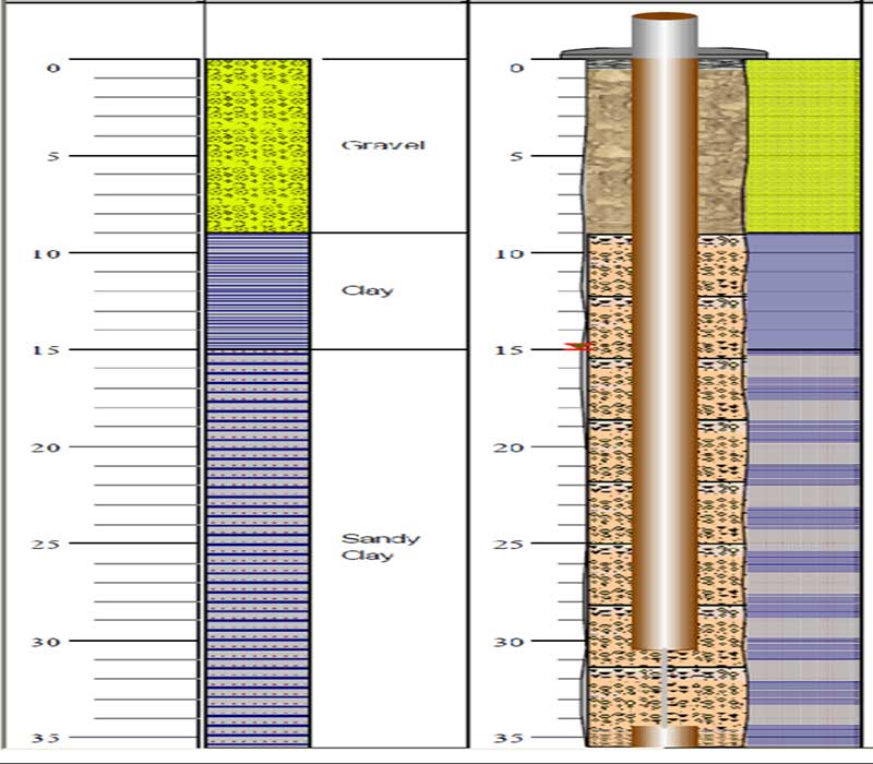
The Purpose of drilling logs

In construction of borehole with a good yield of clear and clean water which is free of contaminants. A Drilled log is needed to determine the depth or location of aquifers or permeable interval for screen installation, the location of impermeable layers, location of sanitary seal above the gravel pack (which surrounds the well- screen)

A drilling log is a written record of the geological formations (soil layers) drilled, according to depth. Soil samples should be taken at regular depths (e.g. every meter) and described during the drilling process. The soil description is then recorded in the form of a drilling log. The drilling log will help to determine:

  • The right aquifer for installation of the well-screen
  • Depth and length of the well-screen
  • Depth and thickness of the gravel pack
  • Location of the sanitary seal

Hydro geological database information

Besides the direct use of drilling logs in the field, drilling logs are also very important to record the hydro geological information of the drill site. For example, if at a later stage other wells have to be drilled in the same area, it is very useful for the drilling team to know the geology, depth of the water table and likely total drilling depth. Previous drilling logs are an essential source of information for these purposes, before the new drilling starts. This information could be important for the choice of the drilling equipment. The drilling logs can be kept together in a file, which is called a database. By taking care to record and preserve good drilling logs, the drilling team will present itself as a professional and skilled team to their clients.

Taking soil sample

The first step in making a drilling log, is to take representative samples of the soil (geological formations) encountered  in drilling. This means: the sample should be a pure piece of the layer that is being drilled at the moment of sampling (avoiding mixing the sample with soil from other layers!). Samples should be taken every meter and/or every time the formation (soil) type changes. The samples should be put on a plastic sheet (write down the depth if the sample is not immediately described), away from the drilling activities. Then described and recorded on the drilling log with the depth at which the soil sample was taken.

DRILLING DEPTH

The final drilling depth is reached when at least 4-6 meter has been drilled into a water bearing permeable sand or gravel layer. It is then recommended to drill two extra meters for installation of the sump which is  a reservoir for particles in the borehole to settle down during the well casing installation process.

FILLING IN THE DRILLING LOGS

Drilling Log

Step 1

Describe samples and write down the depth, name and characteristics  on the drilling log.

Step 2

Then, especially important for those who can not write, hatch the formation column and show  the difference between permeable, semi permeable and impermeable layers by different hatching.

Step 3

Now the well-screen length and depth can be determined.

Step 4

Once the well-screen and PVC casing are hatched in the first column, the exact depths for the annular back fill (i.e. gravel pack, sanitary seal and cuttings) can be determined by use of the drawings on the drilling log.

To resume: filling in the drilling logs is a 4 step process:

  • Describe the samples and depth
  • Indicate permeable and impermeable layers
  • Mark the casing, screen and sump in the column “PVC pipe”
  • Mark the back filling and sanitary seal(s) in the column “back fill”

Groundwater level

When a borehole is drilled ‘dry’, meaning without the use of drilling fluid or With a fluid-drilled where  borehole is kept full of water to maintain water pressure,  the depth of the water table can easily be determined during drilling. The soil that comes out during drilling will be wet when the groundwater level is reached.

DETERMINE THE DEPTH OF THE WELL SCREEN AND BACK FILLING

Once the soil descriptions are hatched on the drilling log, the visible information can be used to determine the exact depth of the well-screen and annular back fill.

Screen & PVC Casing

Well-screen, position and length

The well-screen usually does not exceed a length of 6 meter,  for manually drilled boreholes. Fine materials are often present in the extreme upper and lower parts of an aquifer. Also thin clay layers might exist in the aquifer. To prevent the fines (which may cause turbidity and pump damage) from entering the well-screen it is important NOT to install the well screen at the same level as these fines in the aquifer. In other words; be sure that the whole screen length is installed in a permeable layer, consisting of sand or gravel! To achieve this in some cases the screen length  might be less than 6 meters  (but should generally never be less than 3 meter. Although carefully taken, the exact depth of origin of the soil samples might not always be accurate. To avoid fines from entering, it is wise to install the well screen and back fill with a safety margin of at least 1 meter.

Sump

Sump

After the installation and during the use of a well, some soil particles may still enter the well-screen. The bigger particles (which can cause damage to the pump) settle down to the bottom of the well by gravity. To prevent loss of well-screen surface area, a sump of 1-2 meter in length, with a closed bottom end is attached to the well-screen.

Thickness of the gravel pack

Once the well-screen position is recorded (hatched) on the drilling log, the position and thickness of the gravel pack can be determined. The annulus (open space) around the well-screen is filled with coarse sand or fine gravel of specific size (gravel pack), up to about 1-2 meter above the top of the well-screen. The extra meters are necessary because during the development of the well, the gravel pack will settle (and shrink). It is therefore good practice to include at least 1-2 meter safety margin above the well-screen during installation of the gravel pack.

Thickness of the sanitary seal

When an impermeable layer is drilled through, it is advised to seal (close) again that whole impermeable layer with clay (bentonite) or cement. To be sure the layer is sealed properly, the thickness of this seal should be at least 3-5 meter. If no impermeable layer was found, and the well is thus placed in the first aquifer, the sanitary seal should be installed directly on top of the gravel pack (1-2 meter above the well-screen) and should have a thickness of at least 5 meter.

Cuttings

On top of the sanitary seal, backfilling of the drilling hole is done by using the cuttings (soil which was drilled up during the drilling process).

Sanitary top-seal

Also a sanitary top-seal of 3-5m thickness should be placed from 3-5m below  ground to the surface. it is essential to install a sanitary seal if the well needs to yield good quality water. The sanitary seal can consist of cement or bentonite pellets (the volume of the bentonite pellets will increase many times when it gets wet, and so it seals the hole by expanding). Also natural swelling clays can be used, but they are more difficult to handle than processed bentonite. In many countries bentonite pellets are expensive. In these cases it is recommended to use a cement-water mixture (cement grout). The water and cement are mixed until a thick slurry is created (26 liters of water to one 50 kg bag of cement will make about 33 liters of cement grout). If cement grout is used as a sanitary seal, first a half meter of clay should be back filled on top of the gravel pack to prevent the grout from penetrating the gravel pack.

Talk to us for your upcoming project in Water Borehole Drilling

Geodata Evaluation & Drilling LTD. offers water borehole drilling services. Let us handle the project for you. contact us at www.geodatadrilling.com Phone: +234 8037055441

Water Borehole Rehabilitation

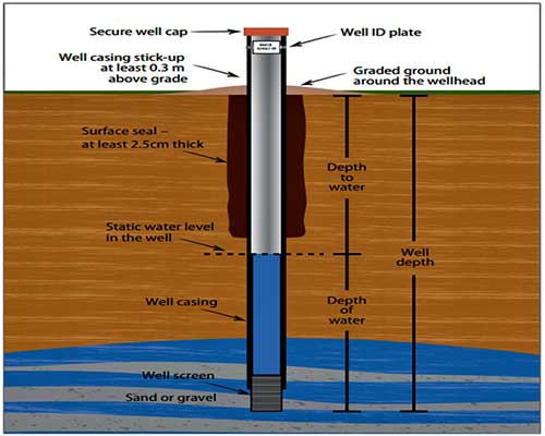
Borehole and well rehabilitation involves restoring and reclaiming a well or borehole which is either no longer in use or has a poor flow rate or performance back to its original condition and in some cases improving its performance and its original output.

Rehabilitating a well or borehole is often the most cost effective alternative to re-drilling a new borehole at a different location and this can be done for a variety of reasons including:

Reduced water flow, therefore insufficient water.

Groundwater pollution

Deterioration in water quality resulting in cloudy, discoloured or dirty water.

Limescale deposits

Iron build up on pumps

Drop in the water table level resulting in reduced output or a dry well.

Borehole collapse due to poor construction.

Cross contamination and lack of cleanliness around the well

Step 1. Before borehole rehabilitation, determine the characteristics of the well (depth, diameter). Also question the users: How deep was the well originally? What was the former yield of the well in comparison to the current one? For drilled wells, determine the pH-value. Ideally, the pH should value 7 or less. If it is above 7, add one litre of vinegar or citric acid to the well and re-test before proceeding

Step 2: Cleaning: Remove the pumping mechanism or lifting device and undertake any cleaning and repairs to the head walls, drainage curtain, sanitary seal, cover and lifting device. For cleaning, use a chlorine solution.

Step 3: Use Jetting method to remove all polluted water, sediments and debris from the well by jetting method. After the removal of polluted water, sediments, and debris, operate the pump for about an hour to remove any suspended fines caused by the jetting process.

Step 4: Clean the well chemically (only if necessary). The chemicals are selected according to the present type of contamination. The selected chemicals are placed in the well and agitated frequently for 24 to 72 hours. The well is then dewatered to remove the chemicals.

For iron bacteria and slime, a liquid bacteria acid is effective. If the bacteria problem is persistent, some more aggressive chemicals are used, such as muriatic acid and hydroxyacetic acid. For clogs with carbonate scale, sulphamic acids are used with inhibitors and modifiers.

Step 5: Disinfect the well. The most common method of disinfection is chlorination. The chlorine compound most commonly used is high strength calcium hypochlorite (HSCH) in powder or granular form, which contains 60 – 80% chlorine. Each chlorine compound has a different amount of usable chlorine depending on the quantity of time the product has been stored or exposed to the atmosphere (GODFREY & REED 2011: Wells).

The amount of chlorine solution (i.e. water with chlorine) that must be poured into the dug or drilled well equals the amount of water that is currently present. First, calculate the amount of water inside the well:

Volume [litres] = 800 * D * D * h; where:

D: diameter of the well [metres]

H: depth of the water in the well [metres]

Then, dissolve 50 – 100 mg/l of HSCH in a bucket of water, depending on the level of bacterial contamination. Putting more or less chlorine will make the disinfection process ineffective.

Pour the chlorine liquid into the well and allow the water to remain for 12 to 24 hours. For drilled wells, operate the pump until chlorine can be smelled in the outflow before letting it stand. If you also intend to disinfect the distribution network open all outflows (e.g. tabs) until the chlorine smell is detected at each one.

Step 6: Dewater the well: Operate the pump until all the chlorinated water is removed. If you have a chlorine test kit you can check the residual chlorine concentration in the water. It should be reduced to 0.5 mg/l or below. Alternatively, pump the water until it no longer smells of chlorine.

Step 7: Seal the top of the well using a sanitary seal (e.g. made of layers of clay). Construct a drainage apron and head wall around the well to prevent surface water, insects and rodents from entering the well. Provide a cover for the well.

If your borehole whether it be domestic or commercial is suffering from poor water quality or quantity then rehabilitation works could be the solution to restore your well and increase its performance and life expectancy.

Talk to us for your upcoming Water Borehole Rehabilitation

Please contact us at www.geodatadrilling.com Phone: +234 8037055441 for free advice. GEODATA EVALUATION & DRILLING experienced team will identify what could be the cause of the problem and offer the most economical solution to bring your borehole back to its optimum condition.

Methods of drilling water boreholes

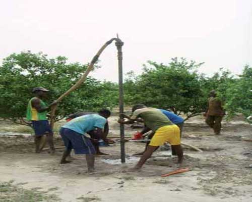
Once a borehole drilling has been decided and a suitable site selected, the proper drilling method must be chosen. Generally, drilling equipment consists of a mast from which the drilling components (tools, drill pipes and cable) are suspended and, in most cases the drill pipes are driven into the ground. It can be manual or powered driven method. The following are common methods of drilling for water:

A) Hand-auger drilling

The hang auger consists of extendable steel rods, rotated by a handle. A number of different steel augers (drill bits) can be attached at the end of the drill rods. The augers are rotated into the ground until they are filled, then lifted out of the borehole to be emptied. Above the water table, the borehole generally stays open without the need for support. Below the water table a temporary casing may be used to prevent borehole collapsing. Drilling continues inside the temporary casing using a bailer until the desired depth is reached. The permanent well casing is then installed and the temporary casing must be removed. Augers can be used up to a depth of about 15-25 meters, depending on the geology. Advantage: They are cheap equipment and easy to use above groundwater table; Disadvantage: It may be difficult to remove the temporary casing; Geological application: Limited to Sand, silt & soft clay.

B) Jetting

A method whereby water is pumped down a string of rods by motor water pump from which it emerges as a jet that cuts into the formation. Drilling may be aided by manually rotating the drill string or by moving it up and down in the hole. Cuttings are transported up by circulating water between the drill pipe and the borehole wall.  The drill pipe may simply have an open end with a constructed drill bit added. Mud additives can be added to the water in order to prevent hole collapse and reduce loss of working water (drill fluid). Jetting (with rotation) can be used up to depths of 35-50 meters. Advantage: Drilling is very fast in sand; Disadvantage: A lot of working is needed at once; Geological application: Limited to sand and thin layers of soft clay.

C) Sludging

This method, which may be described as reverse jetting, involves a pipe being lowered into the hole and moved up and down with a lever arm. A one-way valve (such as someone’s hand at the top of the pipe) provides pumping action as water is fed into the hole and returns (with debris) up the drill pipe. There may be simple metal teeth at the cutting end of the pipe, and a small reservoir is required at the top of the hole for re-circulation. Mud additives can be added to the water to prevent hole collapse and reduce loss of working water (drill fluid). Sludging can be used up to depths of about 35 meters. Advantage:    Easy to use and temporary casing is not needed; Disadvantage: Working water has to be maintained during the drilling process. The level of the water table is not known during drilling; Geological application: Sand, silt, clay, stiff clay and softer-consolidated rock formations (weathered laterite).

D) Manual Percussion drilling

MANUAL PERCUSSION uses a heavy cutting or hammering bit attached to a rope or cable and is lowered in the open bore hole or inside a temporary casing. Usually a tripod is used to support the tools. By moving the rope or cable up and down, the cutting or hammering bit loosens the soil or consolidated rock in the borehole, which is then extracted by using a bailer. Just as with hand augering, a temporary casing of steel or plastic may be used to prevent the hole from collapsing. When the permanent well screen and casing are installed, this temporary casing has to be removed. Manual percussion drilling is generally used up to depths of 25 meters. Advantage: Drills hard formations; Disadvantage: The equipment can be heavy and expensive. The method is slow, compared to other methods; Geological application: Sand, silt, stiff clays, sandstone, laterite, gravel and small stones.

E) Percussion drilling (Mechanical)

Mechanical winching obviously improves the effectiveness of percussion drilling (light cable tool rigs), and a number of useful choices are available. One example is the Forager 55 cable-trailer rig: weighing only 400 kilograms, it can be transported easily to inaccessible sites. The tripod frame can be erected by one person; and the heart of the system is a small free-fall winch, which hoists and drops the tool-set to drill the hole. Power can be provided either mechanically or hydraulically.  However, this kind of rig is not adapted to hard formations or sediments containing blocks. In collapsible formations, the drilling depth is limited by the hauling capacity of the equipment used to retrieve the temporary casing that maintains the walls of the hole.

F) Heavy duty cable tool

Heavy-duty cable tool percussion drilling rigs are truck or trailer-mounted and powered by a large diesel engine driving a cable winch. To add extra weight and drilling power, a ‘sinker’ – or heavy solid steel bar – is fitted above the chisel- like cutting tool. This usually improves borehole straightness and verticality. Percussion rigs allow operators to vary the number of strokes per minute and the length of each stroke, to optimize penetration in hard or soft rock conditions. By adding water, cuttings are removed from a percussion-drilled borehole in the form of slurry and by means of a ‘bailer’ (heavy steel tube with a non-return ‘clack’ valve at the bottom). Softer, unstable formations such as sands or clays may require a combined hollow cutting and bailing tool.

G)  Rotary drilling

Rotary drilling uses drilling mud (mixes of water, bentonite clays, polymers, and additives) as the circulation medium. In the rotary mud system, drilling fluid or mud is pumped down through the drill pipe and out through nozzles in the bit. As the bit penetrates the formation material, the drilling fluid circulates continuously and removes the cuttings. The fluid also serves to cool and lubricate the bit. The mud fluid then flows upwards in the annular space around the drill pipe to the surface, carrying the cuttings with it in suspension. At the surface, the drilling fluid is conditioned before being recirculated down the hole. Properly conditioning the mud helps to prevent down-hole problems.

The basic fluid normally used for rotary drilling is water, to which specific chemicals and other additives can be added to increase the density or viscosity to improve hole support. The fluid can also be weighted to control artesian pressures. The mud forms a membrane that inhibits flow through the walls of the hole, and the internal pressure of the mud provides structural support to the hole wall. The technique is useful for drilling operations in soft, unconsolidated formations and deep boreholes.

Talk to us for your upcoming project in Water Borehole Drilling

Geodata Evaluation & Drilling LTD. offers water borehole drilling services. Let us handle the project for you. contact us at www.geodatadrilling.com Phone: +234 8037055441

« Older posts

© 2023 geodata & Drilling

Theme by Anders NorenUp ↑