How to Drill and Construct Deep Water Borehole
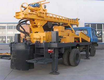
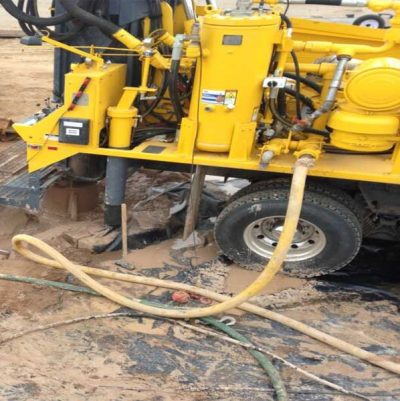
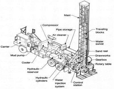
If you want to know how to drill and construct deep water borehole, continue reading. After Drill-Rig Setup, connect the discharge piping. Depending on the type of drilling operation, connect either the air compressor or the mud pump to the standpipe on the mast.

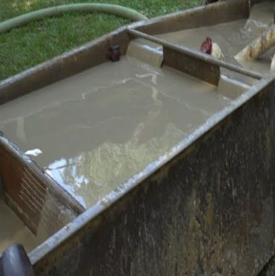
- Install or dig a mud pit, whichever is applicable. Make the appropriate connections to the mud pump to ensure continuous circulation of the drilling fluid.
- If you use rotary drilling with mud, connect or place the suction line of the mud pump in the mud pit and fill the pit with water. Close the standpipe valve and prime the mud pump. Mix the drilling fluid in the mud pit by slowly circulating fluid through the mud pump.
Before you start drilling, you must select a drill bit. Consider the well diameter and the type of formations you will drill through.
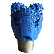
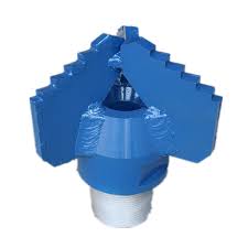
The types of bits are Drag bits: Use for soil, unconsolidated materials usually found near the surface. Tricone roller-rock bits. Use for a variety of materials from soft formations to hard rock. (The bits are available in different degrees of hardness).
Starting the Drilling Operation
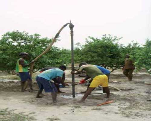
The first operation is spudding in (starting the borehole).
Drive Mechanism for Rotary Rigs
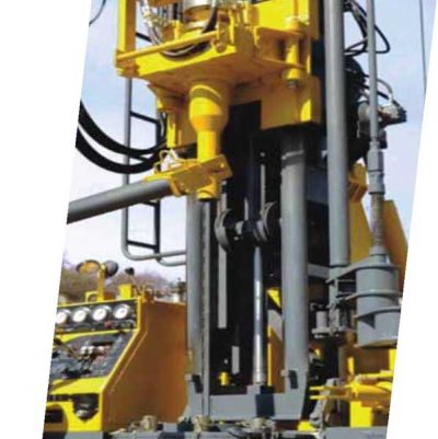
The drive mechanism for drilling operation is provided either at the rotary table Kelly drive (table drive) or at the swivel (top head drive).
On rotary rigs with top head drive mechanism, the bit with drill collar and subsequent drill pipes are connected directly to the drive shaft of top head drive. This process facilitate fast drilling speed and short auxiliary time for drill pipe connection – Step 1 to Step 5 below are not applicable in top head drive rotary rigs.
Follow This Steps and Learn How to Drill and Construct Deep Water Borehole
Step 1. Make up the drill bit on the Kelly and lower the bit to the ground.
Step 2. When the bit contacts the ground, engage the rotary table and clutch to start drilling. (Ensure to start drilling in true vertical direction. Straightness is particularly important for water boreholes in which long strings of casing and screens may have to be installed with a gravel pack filter).
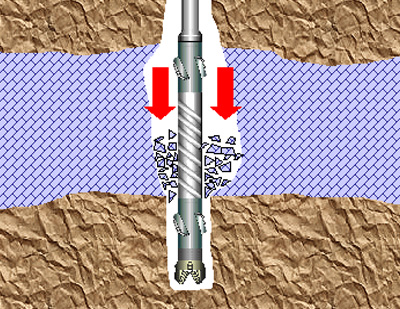
Step 3. After the borehole advances 6 to 12 inches, engage the mud pump to start circulating the drilling fluid (which will be mud or air).
Step 4. After drilling down the kelly, stop the rotation and raise the kelly about 4 inches off the bottom of the borehole. Circulate the drilling fluid until all drill cuttings are removed.
Step 5. Disengage the mud pump, raise the Kelly, and remove the bit.
Finishing the Operation
After spudding in, use the following steps to finish the operation:
Step 1. Makeup the bit on a drill collar. Suspend the collar and bit in the borehole using the hoist or sand line. Support the drill collar in the hole using slips.
Step 2. Clean and lubricate the threads on the Kelly bar and makeup the Kelly to the threads. (On top head drive rigs, you makeup the drill string to drive shaft of drive head).
Step 3. Remove the slips, and lower the kelly so that the drive bushing engages the rotary table and that the tool string is lowered to the bottom of the borehole.
Step 4. Engage the mud pump again and continue drilling. After drilling down the kelly, circulate the drilling fluid until the cuttings are removed. Raise the tool string until the tool joint is 4 to 6 inches above the rotary table.
Step 5. Disengage the mud pump and set the slips to support the tool string. Disconnect the kelly from the string and set the kelly back to the cradle position.
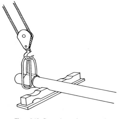
Step 6. Run out the sand line, remove the end cap, and connect a hoisting plug to another drill collar or to a joint of drill pipe.
Step 7. Lift the drill steel with the hoist line or sand line and place the hoisting plug on the drill steel
Step 8. Remove the lower end cap. Clean and lubricate the threads. Make up the threads to the string in the hole with pipe wrenches.
Step 9. Lift the entire string slightly and remove the slips. Lower the string until the tool joint is 4 to 6 inches above the rotary table and the slips are reset.
Step 10. Make up the kelly to the tool string, remove the slips, engage the mud pump, lower the string to the bottom of the borehole, and continue drilling. Repeat the process until you reach the desired depth.
Step 11. Reverse the process to come out of the borehole.
Reaming – After drilling a drill stand down, it is advisable to back ream and enlarge the existing hole.
Installation of Surface Casing
If the borehole has a tendency to cave in during drilling (when drilling in loose, unconsolidated materials.) install surface casing when drill to the desired depth.
When installing the casing before the well screen, such as surface casing, the casing must be larger than the screen. Therefore, use a larger drill bit than the one used to complete the screen portion of the borehole. The decision to use surface casing should be made before mobilizing and should be based on the geologic information about the site.
Use the following steps to install the surface casing:
Step 1. Drill the borehole to a predetermined depth, and remove all the cuttings by circulating the drilling fluid. Withdraw the drill string and remove the bit.
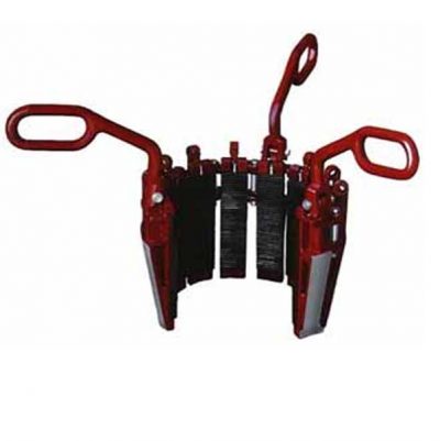
Step 2. Set the kelly back in the cradle. Connect the elevators to the first section of surface casing that is lifted over the borehole by using a casing elevator and the hoist or by using a sand line.
Step 3. Lower the casing into the well and set the slips, which suspend the casing in the well, in the spider bowl.
Step 4. Disconnect the elevator. Hoist the next casing section with the elevator, and place it in the first section. Join the two sections. Slightly lift the string of casing, and remove the elevator from the lower section. Lower the casing, and repeat the process until you reach the surface casing depth in the well.
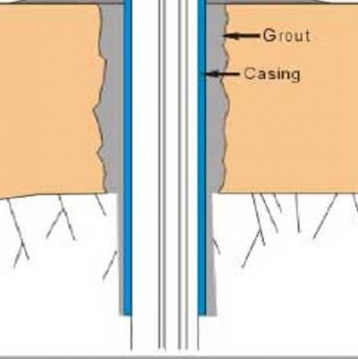
Step 5. Grout the casing in place with a cement grout. After the grout sets (about 24 hours), resume drilling operations using a drill bit that will fit inside the surface casing. Drill the well to the desired depth, case and screen the lower section of the well using the single-string method. (With this method, you install the casing and screen (that have been joined) in a single assembly).
Borehole logging
For a borehole to be properly logged, the driller and supervisor need to know its exact depth at all times. This is necessary for the calculation of drilling charges, and while designing the borehole. First, make a note of the length of the drill bit and of any other tools that may be used to drill the hole. Put the bit on the ground and make a chalk mark, ‘0,’ on the first drill pipe against a suitable fixed point on the rig and at a known height above ground level, such as the drilling table (which centralizes the drill pipes in the hole). From then on, marks can be made on the drill pipe at regular intervals – say, every half meter – to record the depth of drilling and to assist in the logging of penetration rates.
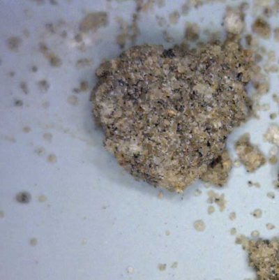
Formation Sampling
Formation samples need to be obtained as drilling proceeds: the usual sampling interval is one meter or every stand drilled. There will be a slight delay as formation fragments are lifted to the surface by the circulating mud, but ensure to make a rough estimate or calculation of the up-hole lag time and actual depth at which cuttings were derived. Cuttings obtained from the shallow mud channel near the borehole should be washed in water to remove mud, and laid out in order (by the depth at which each was acquired) on the ground or in a sample box with separate compartments for each sample. They can then be logged (Identification of lithology and description with respect to depth) by the supervisor or site geologist and bagged if required. Samples should, of course, be labelled correctly with all information relevant to the job in hand.
The main attributes of a borehole log are accuracy and consistency; a good set of logs can be a useful resource when planning future drilling programs. Drillers must keep their own logs and notes and, as is often stipulated in contracts, these should be accurate; however, in practice, they cannot always be relied upon, especially if the supervisor is absent from the site for a period.
All geological samples and water strikes should be logged by the drillers and the supervisor, as this important information will be required for designing the borehole and the equipment to be installed.
Full borehole logging may also include geophysical logging, which is normally carried out only after a well has been completed.
Geophysical Logging
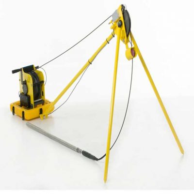
Information about structural features and geological formations in a borehole can be remotely obtained by geophysical borehole logging techniques. The object of well logging is to measure the properties of the undisturbed rocks and fluids they contain. Geophysical logs can provide information on lithology, the amount of water in a formation, formation density, zones of water inflow, water quality, and other in situ parameters that cannot be derived from highly disturbed drilling samples. A suite of geophysical log data, including deep-penetration methods, will more or less complete the technical description of a borehole, but geophysical logging is a specialized field best left to geophysical contractors or hydrogeological consultants. A logging unit consists of a power supply, a receiver/data processing unit, and a cable on a powered winch that lowers special sensor probes (‘sondes’) into the borehole to measure various properties. The cable contains multi-conductors that transmit signals to the receiver console. Data, processed by computer, can be shown as a geophysical record on a graphic display, which should consist of a number of different structural, formation, and fluid logs. Specialized software packages enable manipulation, interpretation, and comparison of data. Multiple-sonde geophysical (‘suite’) logging can provide a substantial amount of information about the sub-surface conditions in and around a borehole.
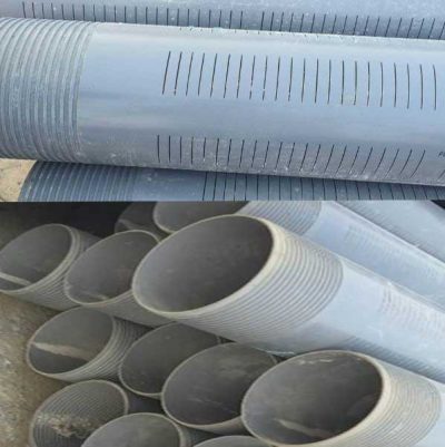
Casing and Screen Installation
You can use the following method to install screens:
Step 1. Place a casing section in the well. Cap the casing or the screen on the lower end so materials from the bottom of the well will not enter the well. (Depending on if the casing or screen is designed to install at the business end of the borehole (Total depth – TD)
Step 2. Suspend a screen section over the well and attach the screen section to the casing section.
Step 3. Lower the screen and casing section. Suspend them in the well either by the elevator resting on the rotary table or by slips in the spider bowl.
Step 4. Add casing until the screen reaches the desired depth.
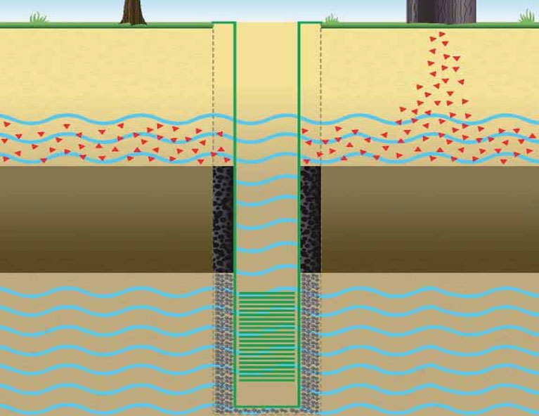
Gravel Pack Filtering and Backfilling
The last procedure when installing screen and casing is to place a gravel-pack filter around the screen and backfill material around the casing. If you place the screen in material such as gravel or very coarse sand, you may not need a gravel pack. Place the gravel filter material around the outside of the casing. Deposit the material to the bottom of the well. Add gravel to about 5 feet from the top of the screen. (Use the sounding method to determine the level of the gravel.) Add impervious backfill around the casing from the gravel pack to about 10 to 20 feet from the surface. If you use grout instead of impervious material, add a couple of feet of clay above the gravel to prevent the grout from entering the gravel filter. Bring the grout to the surface.
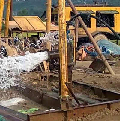
Well Development
Frequently, when a well is first installed, the efficiency (production per foot of drawdown) is not satisfactory, and you must develop the well either by pumping or surging or both. Developing a well removes the remaining drilling fluid, breaks down any filter cake buildup on the borehole wall, and flushes the fines in the formation (adjacent to the grovel pack) into the well. Make sure that you pump the well of all fine sediments and sand with an airlift before installing the submersible pump. If you do not, the pump and components will wear out prematurely. To develop a well, pump or blow the drilling fluid out of the well. Agitate the water in the well to produce an alternating in and out flow through the well screen (or gravel pack). There are several methods available to develop a well.
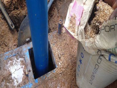
Sanitary Seals.
All wells must have a sanitary seal to prevent contamination from surface runoff. Mix cement grout and place it in the annulus between the well casing and the borehole wall.
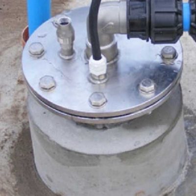
Extend the grout from the surface to the top of the backfill material (30-foot minimum). You should also pour a concrete platform (about 4 feet by 4 feet) around the casing at the surface with the casing extended at least 1 foot above the surface. The upper surface of the slab and the surrounding area should be gently sloping away from the well for better drainage. In addition to a surface grouting, you need to install a well seal (a type of bushing or packing gland) to prevent foreign materials from entering the inside of the well casing. You normally install the well seal when you install the pump, which is after you complete all development, testing, and disinfecting.
Pumping Tests
After installing a well, you should perform a pumping test. The test will show you if the well can produce the required amount of water. If the well is considered permanent, the pumping test should help you evaluate any future performance deterioration. Evaluation parameters are flow rate, time, and drawdown in the well.
Talk to us for your upcoming Deep Water Borehole Drilling Project
Geodata Evaluation & Drilling LTD. offers water borehole drilling services. Let us handle the project for you. contact us at www.geodatadrilling.com Phone: +234 8037055441