How to Supervise deep Water Borehole Drilling
The aim of supervising borehole drilling is to ensure that boreholes are constructed according designed and all the data collected during the drilling are accurately recorded and reported to the relevant agencies. Good supervision is essential for a high-quality borehole, even if a competent Driller is employed. Without good supervision, the quality of the work may be compromised.
A poorly constructed borehole can fail after one year, resulting in wasted investment and disappointed users. Good supervision and quality control of water well drilling by trained professionals (geologist and engineers) to ensure that quality is not compromised are essential for the provision of long-lasting water wells.
A High quality and cost-effective constructed water borehole can continue to function through the lifespan of 30 to 50 years. In some African countries, as many as 60% of water borehole are not working because of poor and substandard construction. One of the best ways to tackle this problem is to improve the quality and professionalism and supervision of water well drilling.
Levels of Supervision
There are three levels of drilling supervision:
- Full-time supervision: a supervisor stays with the drilling team throughout the drilling process, from the inspection to demobilization. On large drilling programs with multiple rigs, several Supervisors are deployed, and they stay in the Drillers’ camp and go out with them each morning. While this supervision level is ideal, the resources needed are not always available
- Part-time milestone supervision: one Supervisor is in charge of several drilling rigs and may only witness crucial stages (milestones) of the drilling. The stages that must be carried out in the presence of the Supervisor need to be specified in the contract document and the consequences of not abiding by them stated. However, the Supervisor is expected to be promptly on site and should not cause undue delays. The milestones are:
- mobilization
- check siting/site selection
- termination of drilling
- lining of the borehole
- borehole development
- pumping test
- demobilization
- platform construction and pump installation (may be delegated, depending on contract).
The ‘Record Keeper ‘, one of the Driller team plays a very important role. He/she is designated to collating the measurements and preparing the forms at all stages of the process set out in the milestones above. This role should be specified in the contract documents.
3. End of contract supervision is not actually supervision but a site inspection when the Supervisor goes through the records and inspects the functionality of the borehole on completion. Where this is the planned level, the supervising role of the community members is particularly important. As in the case of part-time supervision, the role of the ‘Record Taker’ is also very important.
Supervisor Equipment
In all cases, the Supervisor requires a minimum level of equipment and needs to issue site instructions.
Vehicle: Ideally, the Supervisor should be independent. However, this may not be possible, in which case the Driller provides transport to and from the site.
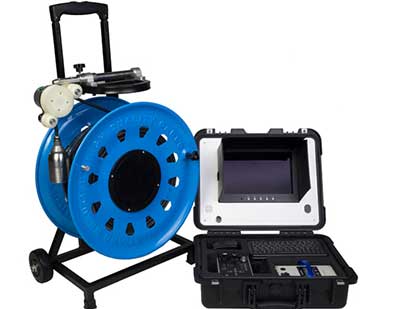
Down-the-hole camera: useful for preventing arguments about casing lengths. In one example, a supervisor carried out a camera survey of several boreholes on a project. The Driller had hurriedly drilled the boreholes not allowing any supervision. Several of the holes were found to be open holes whilst it was specified that they be lined. He had to re-drill them. Cameras are getting cheaper. Every project should have one.
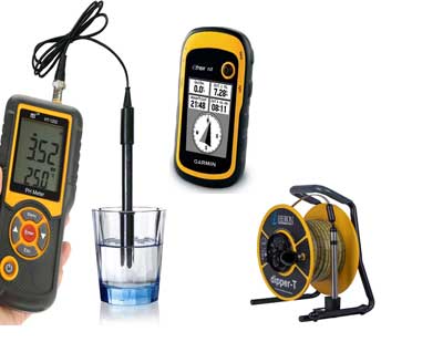
Others: Boots; hard-hat; clipboard; notebook; duplicate book; digital camera; global positioning system (GPS) device; mobile phone; caliper; spirit level (for checking verticality of drill mast and pedestal as well as slope of run-off drains); dip meter; measuring tape; simple calibrated V-plate for measuring borehole yield, magnifying glass; stop watch; pH stick meters and calibrants; iron-checker disc and reagents; bottle of hydrochloric acid if limestone is predicted and a first aid kit. Some other equipment are – depth meter, electronic dipper, tape, EC and PH meters, Global Positioning System (GPS)
Site Instructions
The technical specification for the borehole should include the procedure for site instructions and the consequences for not abiding by them. Site instructions issued to the Driller by the Supervisor should be in writing in duplicate using carbon paper. The Driller should sign on the original and the duplicate instructions. The original is handed over to the Driller, and the Supervisor keeps the duplicate
Community Involvement
Whichever level of supervision is adopted it is essential that community members are involved in the entire drilling process. This should foster the spirit of ownership and understanding of post-construction operation and maintenance. The need for this is even greater when either part-time supervision or end-of- project inspection is used.
Prior to the Driller’s mobilization or at the initial stages of the borehole construction, selected community members (school teachers, health workers, water users’ association members) are taken through the drilling process and are taught how to:
- take the required measurements and record observations;
- keep daily records such as start and end times of drilling and any breaks, and the reasons for them;
- determine depth of drilling by counting the number of drill pipes lowered down;
- record depth and time of the first water strike and other strikes when drilling with air;
- count and record the length and number of casings and screens installed;
- count the number of bags of cement used;
- observe the installation of gravel and the sanitary seal, test pumping and whether borehole chlorination is undertaken.
From the information provided by the community supervision, the Supervisor can build an accurate account of the drilling progress which he/she can cross-check with the driller’s daily log.
What can realistically be expected of the community will depend on their level of literacy and numeracy, too. It should also be clear that community involvement can never replace an experienced supervisor.
Borehole Drilling Workflow – Responsibilities of the Driller and Supervisor
| Steps in borehole drilling | Driller’s responsibilities | Supervisor’s responsibilities |
| 1. Inspection | Assemble equipment & personnel for inspection. | Inspect equipment and interview personnel. |
| 2. Siting | Hydrogeological survey; geophysical survey; submit report. | Check equipment; provide guidance on siting borehole; approve siting report. |
| 3. Pre-Mobilisation Meeting | Raise specific questions regarding the contract requirements. | Together with the client, thoroughly discuss the design, materials and procedures for each step of the contract. |
| 4. Mobilisation | Submit program of work; submit samples of materials; move equipment to site. | Liaise with the community; approve drilling equipment & material; guide driller to site. |
| 5. Drilling | Position and operate the rig, collect sample and reports. | Monitor drilling; advise depth to stop drilling; log the borehole. |
| 6. On-site Design Modifications | Install casing and screen; gravel pack; sanitary seal; report. | Instruct screening and casing depths; ensure gravel pack and sanitary seal properly placed. |
| 7. Borehole development and site completion | Develop the hole; undertake test pumping; collect water sample; disinfect the hole. | Ensure water is clean; proper disinfection; supervise pumping test; ensure samples are taken and platform installed. |
| Demobilisation | Remove all equipment and rubbish from site; report. | Ensure the site is restored to its former state. |
| Complete documentation and handover | Submit all records. Hand over. | Hand over borehole to community. Report. |
Step 1: Inspection
Aim: To verify the capabilities of the Driller before a contract is signed.
| Type of Equipment | Personnel |
| 1 drilling rig | 1 drilling manager |
| 1 compressor | 1 hydrogeologist |
| 1 mud pump | 1 rig operator |
| 1 water tanker | 1 driver |
| 1 support truck | 1 mechanic |
| Adequate lengths of drill pipes to drill the deepest hole | 3 rig assistants |
| Drill bits of the right diameter | |
| Casing, gravel and filter pack, drilling mud |
Step 2: Borehole siting
Aim: To ensure that the borehole is drilled in the right place so that it has water that is accessible to users and protected from pollution.
Step 3: Pre-Mobilization Meeting
Aim: To ensure that the Driller and Supervisor are fully aware of their exact roles and responsibilities and contract details.
Step 4: Mobilization
Aim: To take the drilling project from contract signing to deployment of the drilling crew on site
Mobilization includes the following activities:
- Contract: All borehole projects and supervision are based on a contract agreement. Once the contract has been signed, and pre-mobilization meeting held (Step 3), the mobilization phase starts. Procurement and contract management aspects are covered in Adekile (2012).
- Program of works: The Supervisor should discuss the technical specifications and drilling procedure with the Driller, and discuss and agree the target depths. Then the Super- visor should ask the Driller to submit a program of works.
- Community liaison: It is essential that, before the Driller arrives on site, the Supervisor or Project Manager has had several discussions with the Community about the project and details of the drilling process and their expected obligations and contributions with the main contact persons or Community representatives. The Driller’s representative should meet with the Community and agree a start date.
- Equipment check: The equipment that is to be used by the Driller should be checked to make sure that it is all in working condition, and the same as, or equivalent to, what was examined in the inspection step.
- Materials check: In some contracts, the suppliers, manufacturers, or sources of the material to be used, such as drilling fluid, casing and screens, are specified. The Driller should submit samples of the materials for the Supervisor’s approval. The slot size and wall thickness should be checked, for example.
- Data collection forms: The format of drilling data collection to meet the contract requirements should be agreed on. The final version for copying will be agreed on site between the Driller and Supervisor, and signed by both parties once all the stages of the contract are completed.
- Project filing system: Most of the data could be stored electronically, but hard copies are required for field use. A file (in duplicate) should be opened for every community and all records and data for the community stored in the file. Checklists for all stages of borehole construction (Annex B) are printed inside the flap of the folder and ticked as construction progresses. The original is kept in the office and the duplicate in the Drill Camp or site office.
- Drill camp layout: On large projects where a Drill Camp is set up, the Driller should submit a drawing of the camp lay- out for approval. The main consideration in approving the plan is safety and sanitation: inflammable items should be kept away from likely sources of heat and fire; potential contaminants from water-supply sources and cooking areas; and PVC casing and screens are protected from direct sun- light, which makes them brittle. Where the project covers a large area, Satellite Fly Camps may be needed in the more remote parts to reduce the travelling time to a cluster of borehole sites. The same criteria as for the approval of the Drill Camp plan apply. Once all the above have been completed and approved, the Driller and the Supervisor are ready to move to site.
Step 5: Drilling
Aim: To ensure a high-quality borehole is drilled in a way that is safe and well-documented.
When the driller reach the project site. The following aspects are critical:
- Safety: Drilling is a very hazardous activity. Safety of the workers on site is absolutely vital. Responsibilities for ensuring safety should be clearly set out in the contract. The Supervisor must be constantly vigilant to prevent accidents, and to minimize injuries should accidents occur.
- Rig position: It is essential that the rig is horizontal and the mast vertical, otherwise a bent hole may result. Verticality of the drill pipe should be checked with a spirit level. The rig should be jacked on a robust wooden block so that verticality remains throughout. The rig should be positioned exactly over the pegged site. This is particularly important when the siting is undertaken by a consultant employed by the Client rather than the Driller. If the borehole is dry, there can be no argument that the borehole was not drilled on the specified location. The Driller should ensure that the weight on the drill string is adequate to maintain a straight hole. The use of a heavy drill collar is recommended on at least the first three meters of length behind the hammer. The first drill rod could have welded wings, adding weight as well as scraping to get a circular, straight bore. Also, the Driller should not drill with too much pull-down on the rods.
- Monitoring drilling depth: The Supervisor needs to know the depth of the drill bit at all times to ensure that proper data logging is being done, to know the depth at which to tell the Driller to stop and to compare the drilled depth with the depth recommended in the contract. An unscrupulous Driller can try to rip off the Client either by pretending that the borehole has been drilled deeper than it actually has.
The drilling depth can be monitored by measuring the length of the drill pipe and multiplying the number of full pipes that have gone down into the hole.
Chalk can be used to mark the drill pipe: with the drilling rig set up with the first length of drill pipe and bit fitted, the drill bit is lowered to the ground. The drill pipe is marked “0” at the rotary table that centralizes the drill-pipe, and then chalk marks are made at 1m intervals up the drill-pipe, numbering the marks from 0 up- wards. Measured chalk marks are then made on subsequent drill pipes to be added. This procedure allows anyone on the drill team to know at a glance the exact depth of the drill bit from the ground surface. Note that if the hammer is changed to a longer one after drilling has commenced, the pipes will need to be remarked.
- Penetration rate: This is the time taken to drill a particular interval. A fast penetration rate can indicate an aquifer, although this is not always the case. Less porous strata, such as fresh granites, are often slower to drill through.
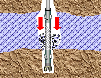
- Drilling fluids & air-lift yield: Drilling fluids are used to remove cuttings from the borehole and to stop the hole collapsing during drilling. The type of fluid should match the drilling method:
Down-the-hole-hammer: compressed air; water and air; or foam;
Rotary drilling: drilling mud (water and additive). Be aware that bentonite clay is commonly used but is outlawed in some countries because it can do permanent damage to the aquifer. Biodegradable polymers should be used;
Percussion drilling: fluids generally not used;
Manual drilling (percussion, auger, sludging, jetting): water.
Monitoring the drilling fluid colour and viscosity is the responsibility of the Driller. Viscosity is checked by measuring the flow rate of the drilling fluid through a Marsh Funnel. The Supervisor should ensure the Driller has a Marsh Funnel and it is properly used. In the case of air-percussion drilling, the air-lift yield should be measured using a V- plate or pipe/container. All observations and measurements are recorded every metre, using the marks on the drill pipe as a guide.
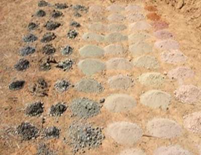
- Drill cutting samples: To collect the samples, the Driller stops drilling, flushes all cuttings in the hole to the surface, resumes drilling, and then collects the cuttings. In air drilling, the samples are caught in a bucket placed in the stream of air jetting from the borehole. In mud drilling the samples are collected by inserting a spade into a small collection pit as the cuttings flow to the main pit. It is the Driller’s responsibility to ensure that the mud pump is of such rating and condition that it can lift the cuttings out of the hole. If the hole is not properly flushed, cuttings may become mixed up and not lifted out so that during lining, the casings do not get to the required depth. The drill samples should be bagged in strong transparent bags, labelled with indelible ink, and stored in a position that they will not be contaminated by site conditions or drilling operations. The label should contain the borehole number and location, sample number and depth. The sample could be collected and stored in a sample box. A photograph of the samples should be taken as a permanent record. In mud drilling, the samples would have mixed with the drilling fluid. The samples should be washed before bagging, but care should be taken in washing soft rock material, such as clays, as they could disintegrate in water.
The depth interval of collecting samples might have been stated in the Technical Specification, but drilling conditions may require that this is reviewed. It might have been specified that samples should be taken at every metre interval. However, in a deep borehole where the formation does not change rapidly, the interval could be increased to three metres. Equally, where there is rapid change in lithology, the Supervisor may change the interval to half a metre.
Description is based on identifying and describing:
the colour
the texture
the grain size and shape
the material
the rock type
For example, samples from a sedimentary borehole could be described as:
0 – 2 m dark grey hard CLAY
2 – 4 m grey brown coarse angular grained loose SAND
4 – 6 m white medium to coarse partially compacted SANDSTONE
6 – 10 m white coarse partially compacted SANDSTONE
10 – 23 m white compacted SANDSTONE
- Strata Log: Drill samples should be described and a strata log prepared by the Supervisor. Different methods are required for describing sedimentary rock samples and crystal- line rock samples. From the strata description, the Supervisor will prepare a graphic strata log which will form part of the final borehole report
- Final borehole depth: It is the responsibility of the Supervisor to instruct the Driller to stop drilling when the right depth has been reached. The decision to end drilling will depend on the information gathered in the course of drilling. The factors will include:
what has been stipulated in the contract, which may be based on Client guidelines with respect to the average borehole depth in the area;
depth of the water strikes/aquifer;
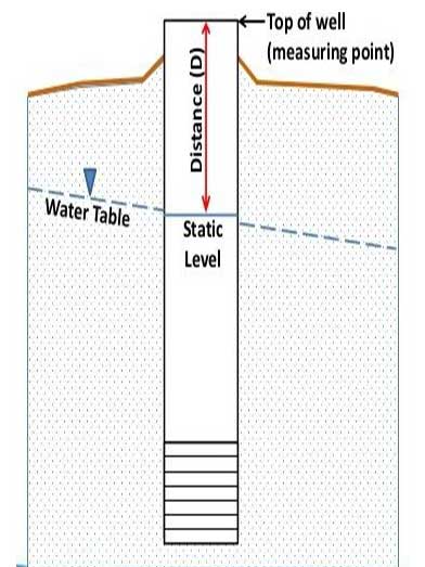
static water levels;
estimated seasonal fluctuations in water levels i.e., changes in water levels as a result of recharge in the wet season(s) and groundwater discharge during the dry season(s);
the estimated yield from the borehole.
The typical signs for adequate yield and drilling depth vary with the type of formation and the drilling method. In the case of a yield which is obviously good, in a well that is to be installed with a handpump the final borehole depth should be at least 5 metres into the aquifer. It needs to allow for proper installation of the pump. It also should allow for 3 to 6 metres of sump (blank casing) below the screen as a sand trap.
However, if the yield is not clearly so good, continue to drill to the next strike horizon, until the yield is sufficient. The yield increments should be monitored with the V-plate. A 6m sump may be suitable where sand and silt are a problem. In cases where there is fine saprolite in the upper sections, these should be cased off to prevent silt from entering and filling the sump.
| Grade | Classifier | Typical Characteristic |
| I | Fresh | Unchanged from original state |
| II | Slightly weathered | Slight discolouration, slight weakening and dislocation |
| III | Moderately weathered | Considerably weakened, penetrative discolouration. Large pieces cannot be broken by hand |
| IV | Highly weathered | Large pieces can be broken by hand Does not readily disaggregate (slake) when dry sample immersed in water |
| V | Completely weathered | Considerably weakened Slakes Original texture apparent |
| VI | Residual soil | Soil derived in situ weathering but retaining none of the original texture or fabric |
For example, the log from a granitic terrain might read as follows:
0 – 6 m orange brown silty CLAY
6 – 16 m grey brown clayey fine SAND
16 – 23 m biotite granite GNEISS IV-III+
23 – 30 m biotite granite GNEISS III+
30 – 43 m biotite granite GNEISS I
- Drill Report: The data from the drilling should be recorded both for the final design and as a reference for future borehole projects. The Driller needs to keep a daily drilling log which should be signed by the rig operator and the Supervisor at the end of each day. The Supervisor should insist that this is done – as Drillers often consider this an unnecessary intrusion into their work. The Supervisor should keep the record of the drilling activities and all measurements in a field note book. The most important data will go into the Casing and Well Completion Form, which will be collated, filed or bound together as part of the final project report and deposited with the appropriate office for future reference. Even data from dry or aborted holes needs to be recorded.
- Step 6: On-site Design Modifications
Aim: To ensure that the finished borehole uses the aquifer efficiently, gives a long working life and low capital, maintenance and operation costs. The Code of Practice for Cost Effective Boreholes (Danert et al, 2010) provides illustrations of different borehole designs. The provisional design should precede the signing of the contract, because the design gives rise to the specification. The specification informs the Driller what to bring to site. Any design work on site involves modifications to, or finalization of, the design.
The Supervisor is responsible for on-site design modifications. Every borehole design is unique because it has to be adapted to the local geology, which cannot be predicted with absolute certainty. Borehole design involves selecting the appropriate dimensions and materials of the borehole, i.e. depth, casing and screen type and diameter, depth intervals of installation, and gravel pack zone. Borehole design factors are set out in Check- list 5 and described in further detail below. Most of the parameters listed above would have already been taken into consideration when writing the technical specifications of the borehole, but the information gathered in the course of drilling will steer the final design.
- Depth: Taken from the Drill Report;
- Formation: What type of aquifer is the borehole taking water from? Use local geological expertise and mapping where possible, but in general the three aquifer types are: Basement Complex; Consolidated sediments; and Unconsolidated sediments;
- Yield: A borehole only needs to be drilled to a depth where the required yield can be sustained without contamination from surface water. Table 4 gives the ranges of yields from different formations. Selection of the other parameters, such as the borehole diameter and lining, should be geared towards meeting the required yield.
- Drilled borehole diameter: The drilled diameter of the borehole needs to be large enough so that pump, casing, screens, gravel pack and sanitary seal can all fit without snagging. For handpump-fitted boreholes there are different schools of thought with respect to diameter, with some favoring smaller diameters, such as 6” to 6.5” and others arguing that this is inadequate to enable gravel packing to be properly installed without bridging. Anscombe (2012), a Driller with years of experience in southern Africa, argues that the reality is that most Drillers simply do not use a tremie pipe when installing gravel pack, with the result that the gravel pack is not properly installed. He thus argues that wells need to be drilled at an 8” diameter. This view has cost implications.
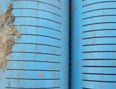
- Casing and screens: Casings are blank pipes which prevent the borehole from collapsing. Screens are pipes which have slotted openings that allow water to flow into the borehole but prevent sediments from entering the borehole. The lining material can be galvanized steel, Polyvinyl Chloride plastic (PVC), Glass Reinforced Plastic (GRP) or bamboo. The two most often used are PVC and steel, and the choice between them depends on the depth of the borehole and the corrosiveness of the groundwater.
A 100mm diameter borehole casing will accommodate a handpump. Submersible pumps may require larger diameter casing depending on the required yield. Pump manufacturers usually prepare sets of curves showing the capacity of their pumps in terms of yield at particular depths or pumping heads and the diameter of the borehole that will accommodate the pump. The Supervisor should therefore check the diameter of borehole casing suitable for the intended pump. Generally, for motorised schemes in rural communities, a 150mm diameter is adequate. In the case of boreholes for small town supplies, or agriculture, a larger diameter will be required. In boreholes that are deep but have high static water levels (i.e. shallow depth of water level), a larger diameter casing, say 300mm, may be installed in the upper reaches of the borehole to house the pump (called the pump chamber), whilst a smaller diameter, 100-150mm, is used to line the lower parts and the aquifer.
In consolidated rock – such as the basement complex – the depth is rarely more than 60m. PVC casing and screens can withstand the pressure imposed by the formation. There is a school of thought that argues that the lower part of the drilled hole could be stable and can be left open and un- lined. In such cases, only the top weathered horizon is lined with a casing. In such holes, the annulus between the casing and the drilled hole should be grouted. However, it has been argued that these holes are not always sustainable, with some prone to siltation.
In unconsolidated formations, the entire borehole is lined to prevent the borehole from collapsing. Where the aquifer is more than 100m deep, the pressure exerted by the water and the rock formation is great, and steel casing and screen should be installed. In deep aquifers with slightly acidic water, Glass Reinforced Plastic may be considered as mild steel could corrode..
The Supervisor should ensure that the casings and screens supplied are new and conform to the specification. If in doubt, the diameter and the wall thickness should be checked with callipers. The Driller should provide a sample of the pipe cut in half, and the measurement taken in the middle. Measuring the thickness at the threaded end will not give the accurate figure. Table 5 gives the dimensions of casings, wall thickness and possible depths of installation from a pipe manufacturer.
It should be noted that drill pipes, casings, screens and other lengths are not always standard. Sometimes they are cut and re-threaded. Often, 3m “standard lengths” are actually 2.95m, or some other length.
| Indication of installation depth m* | Outside x inside diameter in mm | Wall thickness in mm |
| 50 – 75 | 110 x 103.4 (3½’’) | 3.3 |
| 75 – 100 | 110 x 101.6 (3½”) | 4.2 |
| 200 – 300 | 113 x 96.6 (4”) | 8.2 |
| 50 – 75 | 125 x 117.6 (4½”) | 3.7 |
| 75 – 100 | 125 x 115.4 (4½”) | 4.8 |
- Screens: are installed in the aquifer horizon. A borehole screen is a filtering device that serves as the intake portion of boreholes constructed in unconsolidated and semi- consolidated aquifers. The screen permits water to enter the borehole from the aquifer, prevents sediments from entering the borehole and serves to support the aquifer material. Increasing borehole diameter does not have much impact on water flow into the borehole, but increasing the screen length significantly increases the yield. Therefore, as much of the aquifer as cost permits should be screened. There is not much difference in the prices of PVC casing and screen, but stainless steel screens are very expensive and should be used sparingly.
- Screen slot size: The total open area of the screen governs the amount of water that flows into the hole. Slot sizes are not a big issue with handpumps as the required amount of water is relatively small. It is enough to ensure that the aquifer material will be retained by the selected screen slot size. This can be checked by doing a sieve analysis of the aquifer material, but a quick method is to rub a sample of the aquifer material against the screen. An adequate slot size will allow the fines to pass through, whilst the coarse material remains outside. It has been noted that in some southern Africa countries, locally available casing tends to be rather coarse (1mm slot size). This will not always be adequate. If the aquifer is laden with silt, and the slots allow it to pass through, it can result in the wearing of pump seals, and ultimately in siltation of the well. In motorized schemes where a high yield is required, a large diameter screen may be installed as the total open area increases. Water flows freely through a screen with a large in- take area compared to one with limited open area. To prevent turbulent flow into the borehole which could cause encrustation and lower the lifespan of the screen, the velocity through the screen should not be more than 0.03 m/s. The minimum open area in the screen to permit non-turbulent flow can be calculated from the formula:
A = Q/30
where A is the open area in m2 and Q is the water flow in l/s (Macdonald et al, 2005)
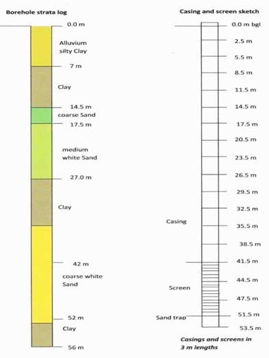
- Installing casing and screen requires great care and attention as it is easy to install blank casing in the aquifer horizon. Once the depth of the borehole and the depth interval for screening are known, a sketch of the proposed assemblage of casing and screen should be made. The casings and screens should be laid out according to the sketch and measured individually, totaled and checked that they conform to the sketch. They should be placed next to the drill collar ready to go into the well. The Supervisor should take a photograph of the layout for the record. Figure 8 shows a sketch of a strata log with casing and screen assemblage in a sedimentary terrain. Once all of the materials are inserted, the drilled depth needs to be reconciled against the casing and screen depth. If the discrepancy is more than 3m, there is need to reconsider whether the screen is actually sitting where it is supposed to, or if there has been some collapse of the well. If something is wrong, the contractor must remove the casing, clean the well, and re-insert it until the Supervisor is satisfied.
Joints should be strong enough to support the entire weight of the casing during installation. Threads should be intact. Both male and female threads should be properly cleaned with a brush and cloth before they are joined. Where non- threaded couplings are used, they should be cleaned and joined together by the solvent cement recommended by the manufacturer. Before the casing is lowered into the bore- hole, the Supervisor should ensure that the recommended time for the cement to set and form a water tight seal is observed.
This is critical, but sometimes the Driller may be in a hurry to leave the site and so shorten the time. Steel casing and screen should be joined by threaded joints that are water- tight. Where welding is used, the weld should be fully penetrating and continuous. If possible, welding of casings should be avoided as the weld can be a point for rusting and casing failure. It is also time-consuming and can put the casing out of true line. In addition, steel casings which are torch slotted on site corrode much easier than those which are bench slotted beforehand.
The casing and screen assembly should be lowered into the hole under the force of gravity. They should never be driven down. In fact, they should be lifted slightly (by 100mm) when they reach the bottom and held there while the gravel is inserted (see point 9). This ensures that they are straight in the hole and not spiraled. In some cases, centralizers are used to align the casing in the hole. A 3m length of sand trap should be part of the well design when boreholes are cased to the bottom and the bottom casing sealed with an end cap.
- Gravel pack: is installed in the annular space between the borehole screen and the wall of the drilled hole. Often, the aquifer material is allowed to collapse against the screen, and the fines are washed out during development. This enables natural development to take place. Where the aquifer material is coarse and mobile, it is the preferred method. However, where this is not possible, artificial gravel packing is used. There are two types with different functions:
The formation stabiliser is coarse sand or river gravel installed in the hole to prevent the caving of formation material and damage to the screen. The material should be carefully chosen and sieved to make sure it is of uniform size and bigger than the slot size of the screen and will not flow into the borehole. It should not contain mica, clay or laterite. Large pieces should be sieved out as they can bridge in the annulus and prevent subsequent gravel from reaching the bottom. Granite chippings should not be used as gravel pack as they tend to be angular and may contain mica or harmful material that leach into the water. The material should be washed and carefully introduced into the hole through a tremie pipe to avoid bridging. It should extend several meters above the screened interval but stop at least 6m below ground surface.
A filter pack is installed around the screen in fine grained unconsolidated formations where an appropriate screen slot size cannot be found. The grain size of the filter pack material has to be selected in relation to that of the formation material. It should be coarser than the aq- uifer sand. The relationship, called the pack-aquifer ratio (P.A. ratio), is calculated from the formula:
Pack Aquifer ratio = 50% size of gravel pack/50% size of
aquifer material
The ratio should be between 4 and 6. For the procedure for sieve analysis and selection of appropriate filter material the reader should consult Driscoll, 1986: 406-409.
It is essential that the casing, screen and gravel pack are available on the site once drilling commences. Once the drilling pipes are withdrawn, the hole has a potential to collapse. Thus the casing and gravel pack need to be placed without delay. Under no circumstances should this wait until the following morning. In the words of Anscombe (2012): “Rods out– casing and gravel in – fast and efficient”.
Step 7: Borehole development and site completion
Aim: To prepare the borehole for use and install the pump and ancillary headworks and structures
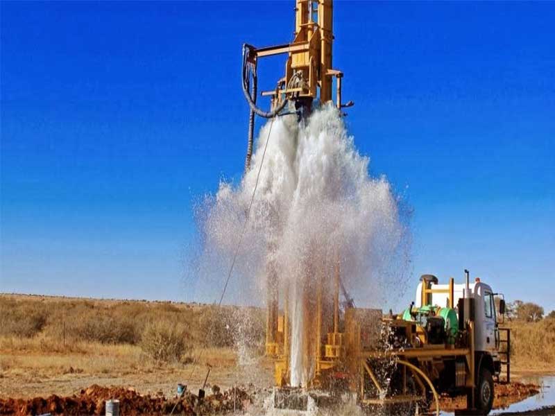
- Borehole Development Method: Borehole development is about cleaning the area of the aquifer immediately around the screens. The method of development should be stated in the technical specification. Figure 9 shows an example of air lifting. Air jetting can use a galvanised pipe, plugged at one end, with 8mm holes along the length so that the air-jet streams in the borehole are horizontal. This pipe, connected to the compressor, is raised and lowered repeatedly over the screen section, finishing in the sump.
- Borehole Development Success: The Supervisor’s duty is to ensure that eventually, the water coming out from the borehole is clear of mud and is sand free. Samples of the water are collected in a clear container and checked to see that there are no sediments collecting at the bottom of the container. As part of this, the Supervisor needs to decide whether a borehole should be accepted or declared abortive. If the borehole is to be aborted, the Supervisor also needs to determine whether the Driller should re-drill the borehole at his own expense or not. This will depend on the terms and conditions of the contract. Although some contracts specify the duration of development (the minimum number of hours that must be spent on developing the hole), this actually depends on the time it takes for the water to be clean. Development should continue until the Supervisor is satisfied that the water coming out of the borehole is clean and sand free. Some boreholes clear within a couple of hours, some may take days to several weeks. Some only clear after several months of pumping. The latter is likely if air-percussion drilling has been used in very loose, clay-rich, silty, micaceous and saturated conditions – in other words not the right drilling technique.
- Sanitary seal: It is essential to prevent contamination of the aquifer and to ensure that the users obtain safe, clean drinking water. When the Supervisor is satisfied with the yield, and development has settled the formation stabiliser or filter pack, then the annulus of the borehole is back-filled with the cuttings, or clayey soil, up to 6m below the ground surface. A sanitary seal is placed in the top 6m to prevent surface water which may be polluted from flowing down the bore- hole annulus into the aquifer. The sanitary seal should be cement slurry in the mixture of 25l of water to 50kg of neat cement, or bentonite.
- Pumping test provides the means to determine the likely success of the borehole in terms of yield and drawdown. It provides information on the properties of the aquifer and on the borehole itself. Two types of pumping test can be conducted. A constant- discharge or aquifer test should always be carried out. This gives information about the drawdown resulting from a spe- cific pumping rate (usually a little greater than the design discharge). The test data can also be interpreted in terms of the aquifer properties. For a handpump, a 3- to 6-hour constant discharge test is adequate. If the borehole is going to serve a large population and a high yield is required, then a longer test of say 24 to 72 hours, or even longer (up to 14 days) may be undertaken.
A constant discharge test provides information about the aquifer in the vicinity of the well. The results of the constant discharge pumping test enable the short term performance of the well to be determined. However, it does not provide any information about recharge, seasonal fluctuations or long term performance. In other words, the pumping test does not give information about the long-term (multi-year) sustainable yield of the borehole. The long-term yield is the subject of groundwater resources evaluations, which focus on recharge and its variability from year to year.
The second type of test is a variable-discharge or well test, also known as a step-test. This type of test is used to determine the hydraulic performance of the well. The data from a step-test can be used to calculate the well efficiency. Step tests are rarely carried out on low-discharge (e.g., hand- pump) wells. However, in the case of a production well or for motorised schemes, the step test is very useful. Provided that the data are kept, undertaking another step test say five years later can enable a comparison to be made. Thus it is possible to find out whether the well has clogged up over time.
In a step-test the well is pumped at a succession of increasing discharges, each carried out for the same duration, typically one or two hours. There will usually be at least four steps, such as at 1/3, 2/3, 1 and 4/3 of the expected design pumping rate of the well.
National or international standards (e.g., BS ISO 1468:2003) should be used in the design of both constant-discharge and step pumping tests. These standards specify test pumping duration, discharge and other aspects of the conduct of the test, including measurement methods. During the pumping test, the Driller usually measures the water levels, discharge and time. The Supervisor is responsible for ensuring that the pumping test is carried out correctly. The Code of Practice for Cost Effective Boreholes (Danert et al, 2010) provides guidance on pumping tests, including a recording format. The pumping rate and the water level are measured at the same time and recorded along with the time of measurement. The pumping rate can be measured with a flow meter, but it can also be established by recording the time it takes to fill a container of known volume. This is measured several times during the test.
There are several ways of analysing pumping test data, and some are quite complicated. However, for the purpose of this guidance note, what is important to the Supervisor is whether the borehole will deliver the required amount of water for the required pumping duration or not. The specific capacity of the borehole, which expresses the relationship between the yield and the drawdown, is the most important quantity, i.e.
Specific Capacity=yield /drawdown (m3/h per m drawdown)
This enables the Supervisor to predict the likely drawdown at different pumping rates and whether the borehole can deliver sufficient water. By calculating the drawdown incurred by different pumping rates, and comparing that drawdown to the available vertical interval between the rest water level and the top of the well-screen (while allowing for likely seasonal water level variations, the effects of extended dry periods, and the interval occupied by the pump itself) it is relatively easy to determine a viable discharge for the well as drilled. A specific capacity of around 1 m3/h per meter drawn suggests that a borehole would be adequate for a handpump – a typical hand pump, drawing 1m3/h would incur only 1m of drawdown in this example.
- Water quality testing: Groundwater from boreholes is often of good quality, but sometimes it may contain contaminants which render it unsuitable for domestic use without treatment. The contamination could be due to minerals dissolved into it from the rocks through which it flowed but results more often from biological contaminants owing to human activities. If the borehole has been properly sited and constructed, it should be possible to eliminate biological contaminants.
The technical specification would have given the parameters to be tested. It is the Supervisor’s duty to ensure that the samples are taken by the Driller in a clean bottle of at least1litre volume. Where the facilities are available, the sample should be analysed on site and then taken to an approved laboratory for further analysis. Note that some parameters change between sampling and reaching the lab and so need to be tested on, or close to the site (including pH, EC, dissolved oxygen, iron and micro-organisms).
In taking the sample, the bottle is rinsed several times with the water being sampled, filled and securely corked and labelled. Some countries have developed drinking water quality standards, and the Supervisor should analyse the results of the water quality testing on that basis. Where there are no country standards, the WHO standards should be used.
Particular attention should be paid to the values of the pH, conductivity, iron, manganese, nitrates, fluoride, arsenic and thermo-tolerant coliforms (TTCs). Groundwater containing iron is often reddish brown or black if manganese is present. It may also taste bitter. It poses no threat to health, but the taste and colour of such water may make it unacceptable to the consumer. Acidic water corrodes metallic plumbing material. High conductivity indicates a high level of dissolved solids, Consumption of groundwater high in fluoride, arsenic and nitrates is toxic.
- Borehole disinfection: The borehole should be disinfected after construction to kill bacteria that might have entered during construction. Chlorine is normally used as the disinfecting agent, leaving a residual in the disinfectant water. The amount of chlorine required depends on the volume of water in the borehole. WHO (2012) recommend that a liter of 0.2% chlorine solution is used for every 100 liters of water in the borehole. This corresponds to a concentration of 20 mg/l. After adding the disinfectant, the borehole should not be pumped for at least 4 hours, if not longer. Care must be taken when mixing and adding chlorine to the borehole as it is poisonous when not diluted.
- Successful or abortive boreholes: The Supervisor will decide whether a borehole should be accepted or declared abortive; and depending on the terms of the contract whether the Driller should re-drill the borehole at his/her own expense or not. The success and suitability of a borehole for acceptance will depend on the following:
a) The depth to pumping water level is critical for hand- pumps as the maximum depth from which it is practical to lift water with a handpump is 80m. RWSN (2007) provides an overview of the operation depths of the various public domain handpumps. Since some allowance must be made for water level drawdown, for a hand pump, the static water level must be less than 80m below ground level. The static water level, together with national pump standards, will determine the handpump to be installed. Depth to static water level is beyond the control of the Driller and he/she should not be penalized for it. Such deep water levels may be encountered in sedimentary terrains. In the case of deeper water levels, motorized rather than hand pump will be required.
b) A dry borehole or one with a lower yield than the desired should be declared abortive. This may not be the fault of the Driller, but if the agreement is that the Driller is only paid for successful boreholes, then re-drilling is at his/her own cost. However, even after attempting drilling in 3 locations in a community, the yield from the borehole may fall short of the minimum allowed. At this stage, a major reassessment of the drilling strategy may be required, with appropriate contracts drafted.
In the meantime, where the shortfall is less than 30% of the minimum specified, and there are no other safe sources of water, then the Supervisor may decide to accept the borehole and complete it if there is no alternative to improve the water supply. However, this may not be a viable long-term solution for the community.
c). The sand content of the water should not be more than 10 parts per million by volume. The Supervisor should collect three 20L samples at the end of the pumping test. The volume of sand in the samples should not exceed 0.2 cubic centimetres. If a borehole should be abandoned because of excessive sand content, then the Driller shall be responsible for constructing another borehole at his/her own cost. The wrong drilling technique or poor gravel packs and well development cause this.
d). The turbidity of the water should not exceed the stipulated limit. In some circumstances, excessive turbidity is due to the characteristics of the aquifer and thus beyond the control of the Driller, who should not be held re- sponsible.
e). Every borehole should be cased straight and vertical. The Supervisor may ask the Driller to carry out a test for straightness and verticality. The Driller should provide the plumb and carry out the test. Should the plumb fail to move freely throughout the length of the casing to the required depth or should the borehole vary from the vertical in excess of two-thirds of the inside diameter of part of the borehole being tested per 30 meters of depth, the borehole should be re-drilled by the Driller at his/her own expense.
f). The Supervisor will determine whether the chemical and bacteriological quality of the water is adequate to serve as potable water supply. If the borehole becomes contaminated because of an action or inaction by the Driller, the Driller should be asked to disinfect the borehole and if necessary construct a new borehole at his/her own cost.
- Platform casting: All boreholes need a concrete apron around the length of casing above the ground for protection against soil erosion and surface water flowing into the borehole. Handpumps also need a concrete platform to hold the pump stand, to drain away spilled water, and for water users to stand upon. There are several designs of pump platforms, some being circular and others rectangular. Some incorporate a drinking trough for animals or a wash pad for laundry. Platform casting is usually undertaken by a dedicated construction team and may take place after demobilization of the drilling equipment. However, the Supervisor will be responsible for ensuring that platform is built to the design specified by the Client in the contract and that the quality of the materials and the construction is good and durable.
Step 8: Demobilisation
Aim: To leave the site clean, safe and ready for use
On completion of the pump installation, the Supervisor must issue a Work Completion Certificate. For this, he has to ensure that the Driller has complied with all the stages, including the final ones, of the contract specification.
Before demobilization, the Supervisor should check that the borehole record has been completed and all information filled in.
Step 9: Complete documentation and handover
Aim: To provide a clearly documented record to help future operation, maintenance and repairs and hand over the completed facility to the Community
The finalisation and submission of drilling records (to the appropriate national authority and local government) is essential. The submission of borehole construction data is Principle 8 of the Code of Practice for Cost Effective Boreholes (Danert et al, 2010). This should be an integral part of the drilling contract, and thus require approval before payment of the invoice.
When the Supervisor is satisfied that the borehole is ready for use, a day is set aside for handing over the borehole to the Community or the Client. It is common practice for the handing over certificate to be signed by three people: the Supervisor, the Driller and the Community representative. During the defects liability period, the Supervisor will monitor and liaise with community members on the functionality of the boreholes during periodic visits. If there are any defects, they will instruct the Driller to make repairs at his own cost, depending on what is specified in the contract.
Talk to us for your upcoming project in Water Borehole Drilling and supervision
Geodata Evaluation & Drilling LTD. offers water borehole drilling and supervision services. Let us handle the project for you. contact us at www.geodatadrilling.com Phone: +234 8037055441