How to carry out Geophysical VES Survey for ground water investigation
what you need to know
The main purpose of vertical electrical sounding surveys is to identify groundwater yielding zones, their geometry, variation in quality (in terms of salinity), and direction of groundwater movement. Groundwater containing various dissolved salts is conductive and enables electric currents to flow into the ground. Thus, the measurement of subsurface resistivity gives information on the presence of water as well as the lithology.
Vertical Electrical Sounding is a geophysical method in which an electrical current is passed into the ground through a pair of electrodes. The potentials developed due to the current within the ground are measured across another pair of electrodes on the ground. Most soils and non-ore bearing rocks are electrically resistive. Soil moisture and ground water are often electrically conductive because they contained dissolved minerals. Therefore the resistivity measured in the ground is predominantly control by the amount of moisture and water within the soil and rock (a function of the porosity and permeability) and the concentration of dissolved solids (salts) in that water. The principle of operation depends on the fact that any subsurface variation in conductivity alters the form of current flow within the Earth and this in turn affects the distribution of electric potential.
Igneous and metamorphic rocks typically have high resistivity values from about 1000 to 10 million Ω.M depending on whether it is wet or dry. The resistivity of these rocks is greatly dependent on the degree of fracturing, and the percentage of the fractures filled with ground water. Sedimentary rocks, which are usually more porous and have higher water content, normally have resistivity values from 10 to 100Ω.M depending on the concentration of dissolved salts. Salt water usually has low resistivity due to the relatively high salt content. This make the resistivity method an ideal technique for mapping the saline and fresh water interface in coastal areas.
Data Acquisition
The common electrode arrays suitable for VES work are the Wenner and the Schlumberger arrays.
What is Wenner array?
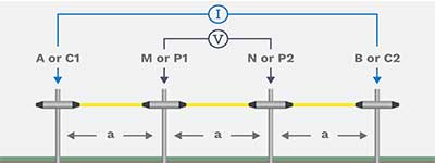
The Wenner electrode array is the simplest of arrays; in it, the four electrodes—A, M, N, and B—are placed in line and spaced at equal distance from each other. The two outer electrodes, A and B, are current electrodes, and the two inner electrodes, M and N, are potential electrodes. Detection of horizontal changes of resistivity is achieved by moving the four electrodes across the surface while maintaining constant electrode separation. The Wenner array is commonly used in profiling for lateral exploration of the ground, like soil testing. The logistic advantage of using the Wenner array when profiling is you only have to move four electrodes for each new measurement along the line.
What is the Schlumberger array?
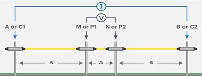
The Schlumberger array is where four electrodes are placed in line around a common midpoint. The two outer electrodes, A and B, are current electrodes that are moved outward to a greater separation throughout the survey for each measurement.
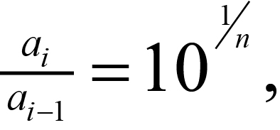
In most interpretation methods, the curves are sampled at logarithmically spaced points. The ratio between successive current electrode spacings can be obtained from the relation:
where
n = number of points to be plotted in each logarithmic cycle.
For example, if six points are wanted for each cycle of the logarithmic plot, then each spacing a will be equal to 1.47 times the previous spacing. The sequence starting at 10 m would then be 10, 14.7, 21.5, 31.6, 46.4, 68.2, which, for convenience in layout and plotting, could be rounded to 10, 15, 20, 30, 45, 70. In the next cycle, the spacings would be 100, 150, 200, and so on. Six points per cycle is the minimum recommended; 10, 12, or even more per cycle may be necessary in noisy areas. The potential electrodes M and N stay in the same position until the observed voltage becomes too small to measure. At this point, the potential electrodes M and N are moved outward to a new spacing. As a rule of the thumb, the reasonable distance between M and N should be equal or less than one-fifth of the distance between A and B at the beginning. This ratio goes about up to one-tenth or one-fifteenth depending on the signal strength.
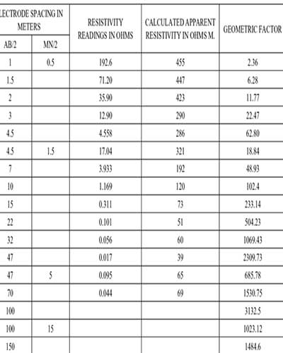
The current is driven into the ground using the current electrodes A and B and the resulting potential difference is measured using the two inner electrodes M and N placed close together. The value of the resistance is measured by Terrameter and the apparent reisistivity calculated by multiplying the geometry factor K. Geometric factor is a parameter which is dependent on the potential and current electrode spacing which is calculated using the equation below.
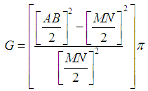
Where:
AB is the distance between the current electrodes
MN is the distance between potential electrodes
π is a constant= 3.142
Apparent resistivity is calculated using ohms law
ρ a = KR
Where, K = Geometric factor
R = Resistance
ρ a = Apparent resistivity.
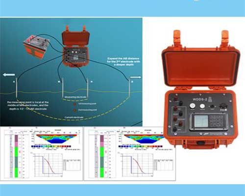
Equipment used is Terrameter, Electrode (current and potentials), Rechargeable battery, Measuring Tape, Cables, Hammer, Global positioning system (GPS) and recording sheet.
Analysis and Interpretation
Vertical sounding curves can be interpreted:
Qualitatively by Study of types of the sounding curves obtained and notation of the areal distribution of these types on a map of the survey area. Each map is prepared by plotting the apparent resistivity value, as registered on the sounding curve, at a given electrode spacing (common to all soundings) and contouring the results.
Quantitative with computer modeling. The first step in the interpretation of a resistivity sounding survey is to plot on log-log sheet a graph of apparent resistivity against the current electrode spacing (AB/2) with the best fit synthetic model curve using the computer software IPI2WIN which is developed for the purpose of data processing, analysis and interpretation. The observed apparent resistivity curves are classified into types with respect to synthetic model curve. This classification is based on the basis of the shapes of the curves, but at the same time it is related to the geological situation in the subsurface (Rock type, grain size, degree of void spaces and amount of water present, degree of weathering etc).The shape of the VES curve depends on the number of layers with corresponding resistivity values in the subsurface and thickness of each layer.
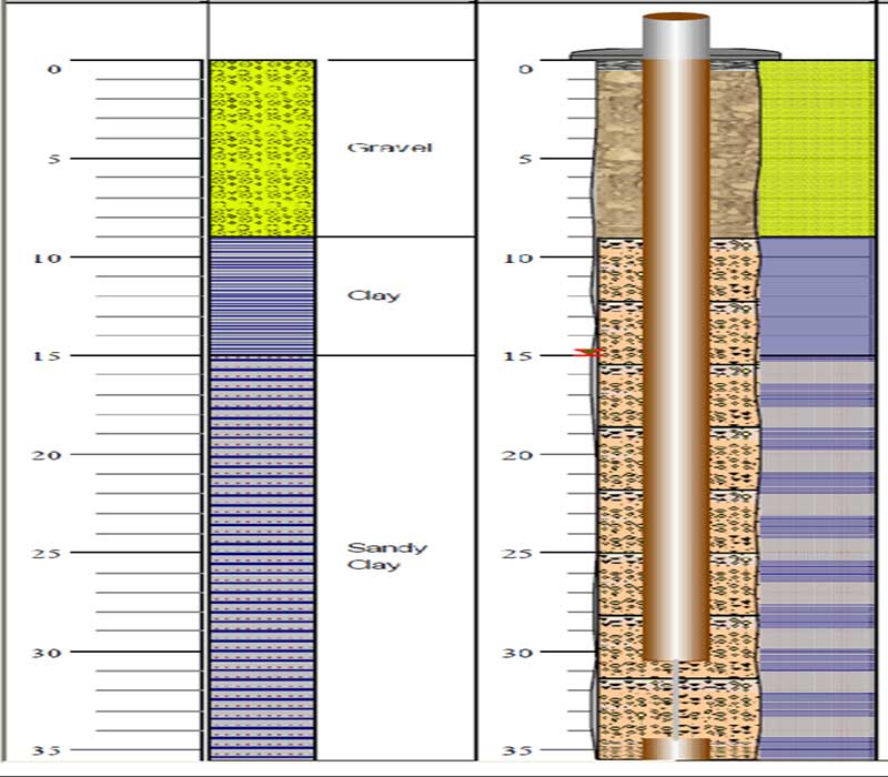
The interpretation should be guided by the information from geologic studies of drill holes, road cuts in the survey area.
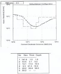
In the above example five geo-electric layers were identified. Using computer assisted interpretation (IPI2win), the geo-sounding synthetic curve will be of the QQH-type (ρa1 > ρa2 > ρa3 > ρa4 < ρa5 ). The topsoil which is the first layer has a resistivity of 141.8Ωm and a thickness of 1.9m. The high resistivity indicates the presences of small amount of water and sand, so the possible lithology is wet sandy clay. The second layer has a resistivity of 53.4Ωm and a thickness of 3.1m, with the amount of the resistivity measured, it shows that the layer is conductive which indicates the presences of a high amount of clay. The third layer has a resistivity of 14.1Ωm and a thickness of 11.9m. The lithology here can also be said to be that of a clayey sand. The fourth layer has a resistivity of 9.3Ωm and a thickness of 21.3m. Due to the low resistivity in this layer the lithology here is clay. The fifth layer having a resistivity of 29.2Ωm and a thickness of 20.4m will have a formation of clay mainly. From the table above one can noticed that there was a decrease in resistivity with increase in depth, though later increases in the fifth layer.
Talk to us for your upcoming project in VES survey
Geodata Evaluation & Drilling LTD. offers Vertical Electric Sounding (VES) to determine actual depth to good ground water zone. Let us handle the project for you. contact us at www.geodatadrilling.com Phone: +2348037055441

Thanks for the help in this question how I can thank you?
I agree with told all above. Let’s discuss this question. Here or in PM.
You were visited with remarkable idea
It not a joke!
The theme is interesting, I will take part in discussion. Together we can come to a right answer. I am assured.
https://batrepairadda.com/products/apl/
The application of the Electrical resistivity method for exploration of groundwater in Aaba residential area, Akure, southwestern Nigeria has been carried out in this study by interpreting acquired VES data via maps 3D imaging and geoelectric sections 2D imaging. This work has provided reliable information on the application of electrical resistivity method in groundwater exploration, which will be indispensable for developing an efficient water supply schemes and groundwater success rate in the study area.
The water yield may be further enhanced where the weathered basement is underlain by fracture zones, porous and deep network of joints and fracture or fissures in the parent rock and some of the greatest water needs occur in regions underlain by basement complex King et al., 1997. Geophysical investigation involving VES was carried out in Aaba residential area in Akure using a Schlumberger array. The study area was chosen because the inhabitants suffer shortage of water for their daily and economic activities due to low yield of surround wells.
What is the MN/2 signifies
MN/2 is the half-spacing of the measurement electrodes use in the calculation of geometry factor.