Advance Sand search methods for Deep water sand dredging
The main components of sand search investigations include initial layout of survey track line patterns, core site selection, selection of personnel and equipment, scheduling, and cost estimates. Exploration for offshore sand and delineation of potential borrow sites mainly involve geophysical and geotechnical or sediment-sampling programs.
Geotechnical Survey
The geotechnical operations include:
- Surface sampling; Samples of seafloor sediments are required to gain a rough idea of sediment types.
- Jet probes and vibrating coring for subsurface sampling is essential for borrow source identification and evaluation. This is usually accomplished by means of a continuous coring apparatus that can obtain cores 7–13 meters in length.
Geophysical Survey
The geophysical operations include:
- Differential global positioning systems (for geographic location)
- Fathometers or Bathymetric survey (for water depth)
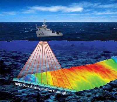
- Side-scan sonar (to show seafloor topography)
- Seismic reflection and sub bottom profilers (to determine stratigraphy, depositional environment, etc.).
- Magnetometer surveys are sometimes required to detect the presence of pipelines and debris buried in the seabed.
Geophysical surveys and geotechnical work is use to establish deposit geometry and the quality and quantity of sand.
Geophysical Methods
Geophysical survey techniques, which use sound waves and high-quality positioning systems on research vessels, gather subsurface geological and geotechnical data in terrestrial and subaqueous coastal environments. Indirect subsurface data, as opposed to the direct sampling procedures (i.e., drilling of boreholes and coring), are obtained during geophysical surveys. Geophysical methods assist in locating and correlating geological materials (i.e., sand deposits) and morphological or topographic features (e.g., coral reefs, sand waves) by determining the acoustic transparency, diffraction patterns, configuration and continuity of reflectors, and apparent bedding patterns.
Acoustic remote sensing provides the only practical means to map and study the surface morphology of the seafloor over large areas and at all depths. Because acoustic waves are generated easily and hardly absorbed in the water column, their reflection off the seafloor relays information that can be used to interpret local morphology.
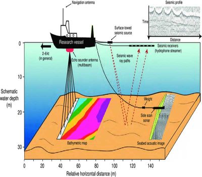
Acoustic waves are the basis of Sonar. Sonar systems are approximately divided into three categories: Echo sounders, Side-scan sonars, and Multibeam sonars. Echo sounders transmit a single vertical beam, whereas side-scan sonars generally transmit two beams, one on each side. Multibeam sonars transmit several tens of beams on each side. These systems can acquire bathymetry or acoustic imagery or both. Echo sounders and multibeam systems are mostly mounted on the hull of the vessel, whereas sidescan sonars are typically towed as ‘‘fish’’ behind the ship.
A single geophysical method cannot provides sufficient information about subsurface conditions without backup or verification from sediment samples (e.g. vibracores) or additional data from other geophysical procedures that corroborate interpretations. Fathometers (or echo/depth sounders), side-scan sonar, and sub bottom profilers are commonly used to collect geophysical data in marine exploration programs All three systems (Echo/depth sounders, Side-scan Sonar, and Sub bottom profilers) which use electrically powered acoustic devices that propagate acoustic pulses in the water, measure the lapsed time between pulse initiation and return signals that are reflected from features on or beneath the seafloor. These systems are widely deployed to obtain information that is useful in the interpretation of seafloor geomorphology, for delineation of bottom features (e.g., ripple marks, sand waves, rock outcrops), and for estimating the nature (grain size, composition) of underlying rock and sedimentary units
- Acoustic depth sounders are used for bathymetric surveys.
- Side-scan sonar images show the areal distribution of sediments, surface bed forms (e.g., wave or current asymmetrical ripples, plane beds, swaley cross-strata, dunes, bar forms, bed form troughs, low-relief bed forms, sand waves), and macro-morphological features such as shoals and channels.
- Sub-bottom profilers show near-surface stratigraphy (sedimentary layering) below the seafloor.
Echo Sounding System
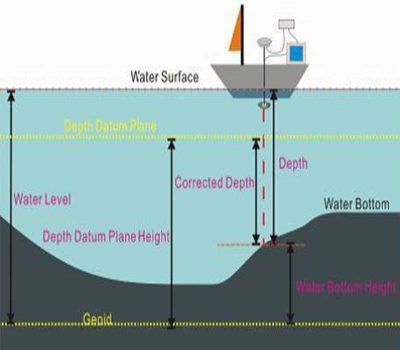
Echo sounders should be calibrated accurately so that observed (recorded) depths can be related to true water depth by establishing an independent ‘‘true’’ reference. Fathometers (echo sounders) can be calibrated by the bar-check method, which should be performed before and after the fathometer survey in an effort to correct velocity variations and index errors in the echo sounding system.
True depth is measured by placing a flat bar or plate, suspended by two precisely marked lines, to a known depth below the transducer. Variations between true depth and the recorded digital or analog depth are used to correct observed depths. Bar checks, taken at sufficient intervals to develop the variations, thus correct velocity variations, vessel draft variations, and index errors in the echo sounding system.
The fathometer or Echo sounder and digitizer are calibrated daily by the bar-check procedure at a convenient increment (usually about 1.5 meters) to the project depths. End of the day bar-checks are again conducted to ensure against drift of the fathometer calibration.
Tidal Corrections
Tidal corrections are obtained from tide gauge readings and are applied to the vertical data. Tide data are generally recorded at 15-minute intervals during the entire survey by an offshore stand (with tide staff and stilling well), which is placed seaward of the surf zone. Tidal levels are read manually by an optical level procedure. Tide gauges are normally set onshore on a pier or some other fixed structure
Bathymetric Survey (Echo Sounder)
Bathymetric surveys are required for many studies of geology and geomorphology in coastal waters including offshore sand searches in attempts to define target areas that might eventually become borrows. Fathometers or echo sounders, are most often used to measure water depths offshore. The distance between the sound source and the reflector (seafloor) is computed as velocity of sound in water divided by one-half of the two-way travel time.
Seismic and Side-Scan Sonar Surveys
Successful sand searches rely on sonar imagery of the seafloor and sectional depth views along track lines that show sedimentary layering. Seismic reflection profiling, calibrated to sand searches with the use of vibracore data, is crucial to the delineation of potential sand bodies in terms of depth and lateral extent. Sonar surveys provide useful proxy data that can be interpreted in terms of smoothness or roughness of the seabed, information that is useful for differentiating rock outcrop from unconsolidated sediments.
Side-Scan Sonar Survey
Side-scan sonar is used to distinguish topographic elements on the surface of the seafloor. Acoustic signals from a ‘‘fish’’ towed below the water surface are directed at a low angle to both sides of a trackline, in contrast to downward-directed echo sounder and seismic reflection signals. The resulting image of the bottom is similar in many respects to a continuous aerial photograph. The image is produced by acoustic beams that are transmitted by the sonar to interact with the seafloor
Seismic Survey/Sub bottom Profiling with the Chirp Sonar System
In geophysical surveys, the distance between the sound source and the reflector is computed as velocity of sound in that medium (rock, sediment, or water) divided by one-half of the two-way travel time. This measurement is converted to an equivalent depth and recorded digitally or printed on a strip chart. A recent development that is extremely valuable to interpretation of bottom-sediment grain size is a signal processing unit that can be interfaced with an echo sounder and used to indicate the size of seafloor sediments in terms of Wentworth or other general classification schemes. This is accomplished by measuring two independent variables, viz., roughness and hardness, from acoustic signals and interpreting these data in terms of sediment type.
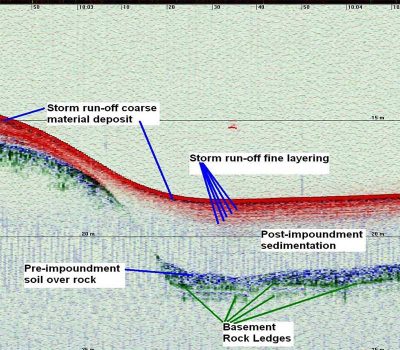
The basic principles of sub bottom seismic profiling and acoustic depth sounding are essentially the same. A lower frequency and higher power signal (to penetrate the seafloor) is employed in sub bottom seismic devices. The transmission of the waves through earth materials depends on properties such as density and composition. The signal is reflected from interfaces between sediment layers of different acoustical impedance. Coarse sand and gravel, glacial till, and highly organic sediments are often difficult to penetrate with conventional sub bottom profilers, resulting in poor records with data gaps. Digital signal processing of multichannel data can sometimes provide useful data despite poor signal penetration.
Seismic reflection profiles are roughly analogous to geological cross sections of sub bottom materials because acoustic characteristics are usually related to lithology.
GEOTECHNICAL SURVEYS
In contrast to geophysical surveys that provide proxy data that must be interpreted (usually in terms of sedimentary structure, architecture, grain size, and composition), geotechnical surveys ( vibracores) collect real physical data in the form of sediment samples. Because vibracoring, for example, collects in situ (undisturbed) sediment samples, it is possible to inspect sediment samples as in-hand specimens from split cores and in thin section under the microscope if necessary. Geotechnical surveys help to support geophysical investigations and, in their own right, provide primary data for reconnaissance exploration and detailed proving of potential borrows. Like geophysical surveys, geotechnical surveys are deployed at various scales and at different levels of investigation as tasked by sand search rationale to help establish salient aspects of the coastal geological framework
General steps in sand search surveys
I. Literature review & sequencing of exploration programs
1. Review of existing literature and data
2. Preparation of design and sequence of exploration program
a. Incorporate available data, information on a regional base map
b. Enumerate various tasks involved in exploration
II. Reconnaissance geological (geotechnical) and geophysical surveys
3. Reconnaissance geological and geophysical surveys
a. Positioning
b. Bathymetric survey (on regional scale)
c. Seismic survey, sub-bottom profiling (on regional scale)
d. Preliminary sampling—mainly grab samplng and a few vibracores
4. Identification of potential target areas for detailed exploration
III. Detailed geophysical surveys
5. Detailed geophysical investigation
a. Bathymetric survey
b. Seismic survey, sub-bottom profiling
IV. Detailed geotechnical survey, data reduction, and determination of sand volume in borrows
6. Detailed geotechnical investigation
a. Detailed surface sampling
b. Detailed subsurface sampling (vibracores)
7. Evaluation of geotechnical data
a. Laboratory analyses
b. Delineation of borrow areas
8. Hazard and archaeological assessment survey
a. Sidescan sonar survey
b. Magnetometer survey
9. Borrow area selection, calculation of the available sand volume.
V. Geotechnical and Geophysical Report preparation
10. Geological interpretation and analysis, raw data in hard copy and digital data in GIS format
VI. Hazards & Archeological Assessment Survey and Report (Cultural Resources)
Talk to us for upcoming deep water Sand Search for dredging project
Geodata Evaluation & Drilling Limited in conjunction with our foreign partners offers deep water Sand Search services for dredging project. Let us handle the project for you. Contact us at www.geodatadrilling.com Phone: +234 8037055441